| Chapter 3. Modules and Networks | ||
|---|---|---|
 |  | |
| Chapter 3. Modules and Networks | ||
|---|---|---|
| | | |
Table of Contents
In MeVisLab, programming image processing algorithms or interactive image/3D scene manipulation is primarily done by establishing networks consisting of modules and connections between them. Modules encapsulate specific algorithms written in C++ and provide an interface in MeVisLab through fields. These fields can represent simple data, such as numbers or strings, but can also handle more complex data, such as six-dimensional voxel images. Fields of modules of the same type can be connected to form networks that represent algorithms on a higher abstraction layer.
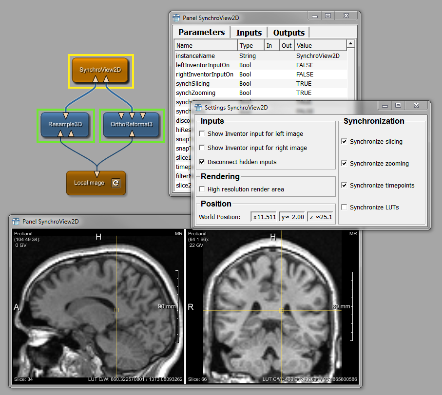
In the following figure, a typical assembly of connected modules in a network, their panels, and viewers can be seen.
The following information can be found in this chapter:
For module and network shortcuts, see Section 4.3.10, “Preferences — Shortcuts”.
There are three types of modules:
Table 3.1. Module Types
| Type | Color | Look | Characteristics |
|---|---|---|---|
| ML module | Blue |  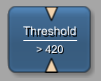 | Page-based and demand-driven processing of voxels |
| Open Inventor module | Green |  | Visual scene graphs (3D) |
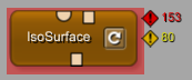
| Macro module | Brown |  | Combination of other module types, allowing implementing hierarchies and scripted interaction |
If a module is invalid, it is displayed in bright red.
The number of warning and error messages printed to the debug console is displayed in the upper right corner of the module. Once the debug console is cleared, the warning and error indicators at the module are also cleared. If the module produces information messages, their number is printed in gray at this position. This enables a network or module developer to find the modules in a network that produce messages quickly.
Table 3.2. Invalid Modules
| Module Appearance | Explanation |
|---|---|
|
| Invalid module |
|
| Macro containing at least one invalid module within its internal network, which could be either a regular module or another macro module |
For information and examples on how to construct networks from modules, please refer to the Getting Started in which image processing pipelines, scene graphs, and macro module creation are discussed in detail.
© 2026 MeVis Medical Solutions AG
| | | |
| 2.2. Views |  | 3.2. Module Network Panels |