| Chapter 7. Creating an Open Inventor Scene | ||
|---|---|---|
 |  | |
| Chapter 7. Creating an Open Inventor Scene | ||
|---|---|---|
| | | |
Table of Contents
In the following chapter, we will walk through the creation of an Open Inventor scene.
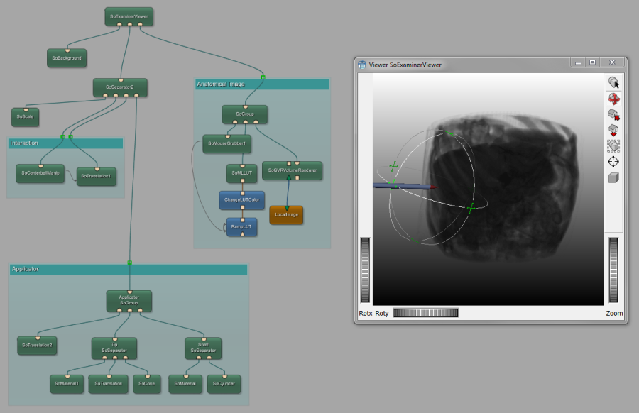
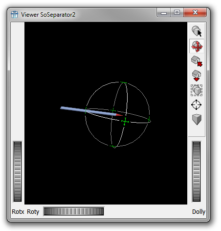
Here a look at what we want to accomplish: a dynamically definable applicator (needle for minimally invasive surgeries) shall be placed at a position and an angle relative to the rendering of an anatomical image.
The applicator shall be able to be moved within the viewer (navigation) and also be able to be repositioned (interaction) with the tip pointing to the body.
The data shall be displayed in 3D mode. In addition, the output shall have the windowing functionality of the standard Output Inspector.
In the resulting network, modules will be grouped; however, this has no effect on the functionality we will build.
Open Inventor is an object-oriented 3D toolkit developed by Silicon Graphics (SGI) offering a comprehensive solution to interactive graphics programming problems.
Inventor scenes are organized in structures called scene graphs. A scene graph is made up of nodes, which represent 3D objects to be drawn, properties of the 3D objects, nodes that combine other nodes and are used for hierarchical grouping, and others (cameras, lights, etc). These nodes are accordingly called shape nodes, property nodes, group nodes and so on. Each node contains one or more pieces of information stored in fields. For example, the Sphere node contains only its radius, stored in its radius field.
The MeVisLab implementation of Open Inventor is based on the original SGI source code that was released to the public in 2000. It is suited for use with MeVisLab but can also be used independently. The MeVisLab modules can be used for rendering and viewing both image data and arbitrary Open Inventor objects as well as for interacting with images. Inventor modules function as Inventor nodes, so they may have input connectors to add Inventor child nodes (modules) and output connectors to link themselves to Inventor parent nodes (modules).
Characteristics of an Open Inventor scene graph:
Scene objects are represented by nodes.
Size and position is defined by transformation nodes.
A rendering node represents the root of the scene graph.
Nodes are rendered in the order of traversal.
Nodes on the same level are traversed from left to right.
All modules that are derived from SoGroup offer a basically infinite number of input connectors (a new connector is added for every new connection). For more information about connecting to an Inventor group node, see Section 3.4, “Connecting, Disconnecting, Moving, Copying, and Replacing Connections”.
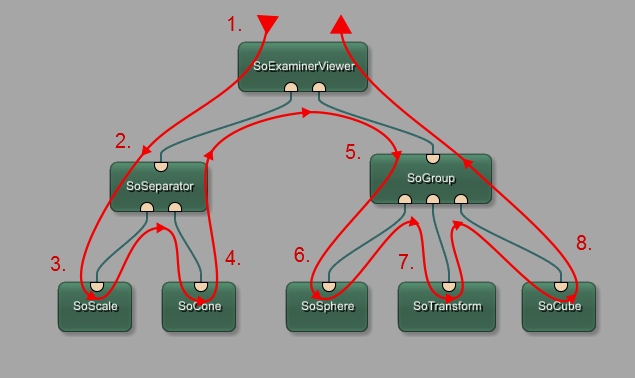
In Figure 7.3, “Traversing in Open Inventor”, the red arrow shows the order of traversal, from top to bottom and left to right. The numbers designate the order in which each module is passed first, from 1 to 8.
Typical functions of Open Inventor modules are:
Draggers and manipulators
Group nodes
Light sources
Transformations
Cameras
3D viewers
Geometric objects (Spheres, Cones, 3D Text, Nurbs, Triangle Meshes, etc.)
Object properties (Textures, Colors, Materials, etc.)
The order of traversal is very important, and its effects will be shown in detail in the following example.
Another important point is that field changes in Open Inventor modules are handled differently to ML modules:
Field changes in ML modules are executed synchronously: The field change leads to an immediate execution by calling its handleNotification(Field*) method.
Field changes in Open Inventor modules are executed asynchronously: The field changes is stored in a delayed queue. In general, it is not known when this queue will be processed. Processing can be enforced by calling MLAB.processInventorQueue().
For further information on Open Inventor modules in MeVisLab, please refer to the Open Inventor Reference and the Inventor Module Help. For general information on Open Inventor, we recommend the following literature:
The Inventor Mentor by Josie Wernecke (ISBN 0-201-62495-8: This book provides basic information on programming with Open Inventor. It includes detailed program examples in C++ and describes key aspects of the Open Inventor toolkit, including its 3D scene database, node kits, interactive manipulators, the Inventor Component Library, which contains editors and viewers, and the Open Inventor file format.
The Inventor ToolMaker by Josie Wernecke (ISBN 0-201-62493-1): The Inventor Toolmaker provides advanced information on extending Open Inventor by creating new C++ classes and customizing existing classes. Detailed examples and discussion show how to create new nodes, actions, elements, fields, node kits, draggers, manipulators, engines, and components.
![[Tip]](images/tip.png) | Tip |
|---|---|
For online links to these books and other resources, see the MeVisLab website (https://www.mevislab.de/ ). |
© 2026 MeVis Medical Solutions AG
| | | |
| 6.4. Miscellaneous |  | 7.2. Creating the Applicator |