| 3.4. Connecting, Disconnecting, Moving, Copying, and Replacing Connections | ||
|---|---|---|
 | Chapter 3. Modules and Networks |  |
| 3.4. Connecting, Disconnecting, Moving, Copying, and Replacing Connections | ||
|---|---|---|
| | Chapter 3. Modules and Networks | |
MeVisLab offers multiple ways of connecting or disconnecting modules in a network. Modules can be connected to each other by connecting their parameter fields or their data fields. Data fields are also called input/output connectors and are located at the bottom/top of the modules in a network. Parameter fields are available on the panel or GUI of a module.
In the following, different methods of handling data connections are shown. Parameter connection handling is not discussed in detail here; for more information about parameter connections, see “Parameter Connection for Synchronization”.
Data connections can be established by dragging/drawing, by proximity, i.e., moving modules close to each other, or by inserting a module into an already existing connection.
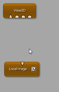
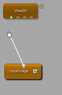
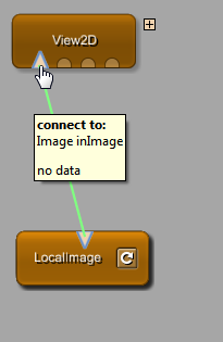
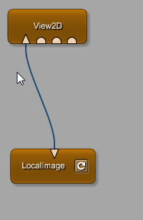
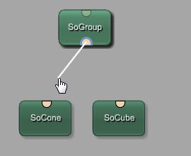
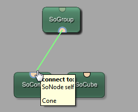
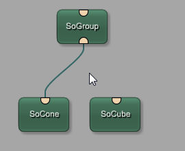
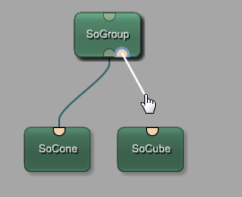
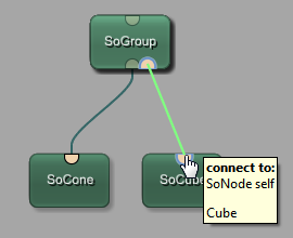
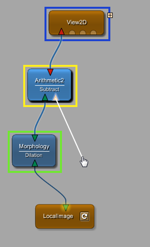
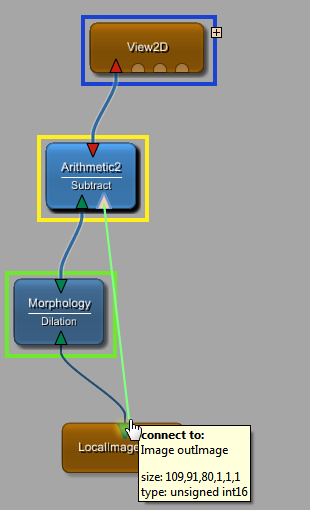
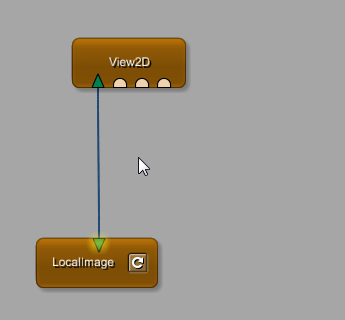
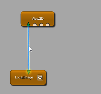
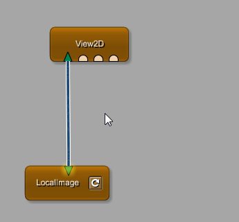
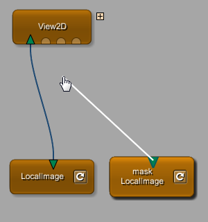
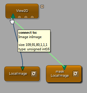
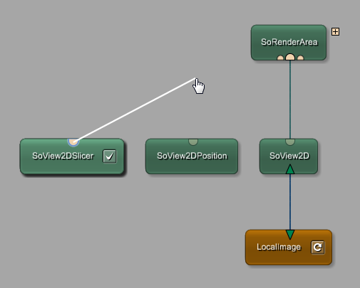
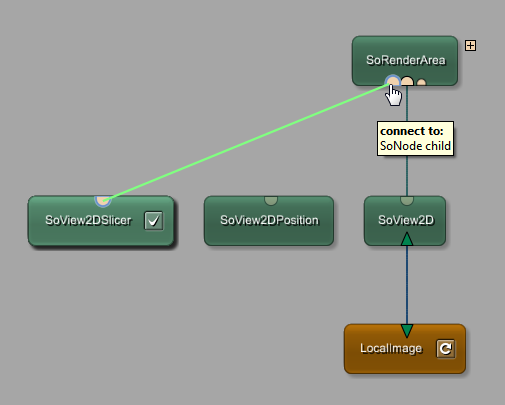
Move the mouse to one of the connectors, click and hold the left mouse button, then drag the mouse to the destination connector. While dragging, an intermediate white connection line is drawn. If the connection is possible, the line turns green. Upon releasing the mouse button, the connection is established.
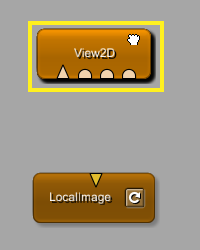
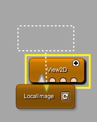
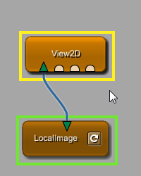
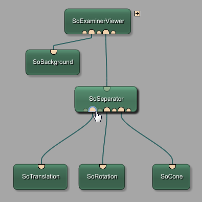
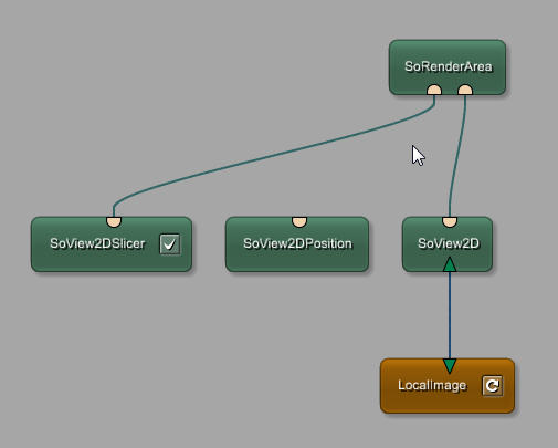
Connecting to an Open Inventor group module (e.g., SoSeparator, SoRenderArea, SoGroup) works the same as described in Section 3.4.1.1, “Connecting by Dragging”.
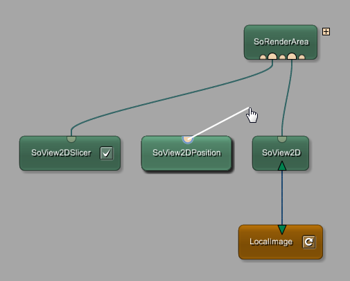
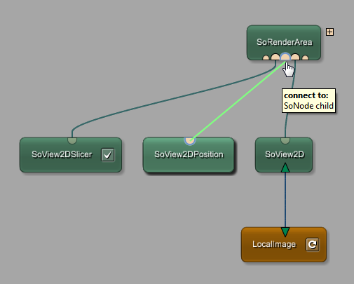
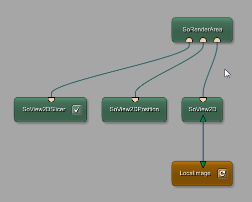
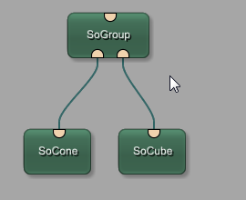
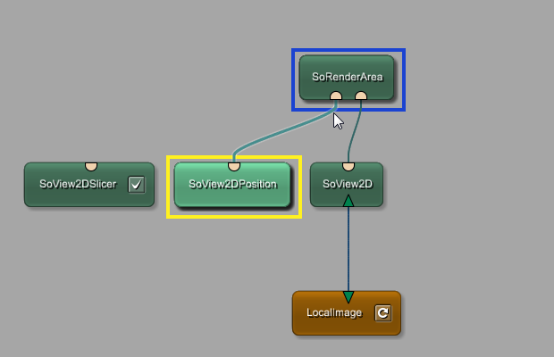
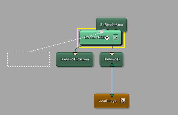
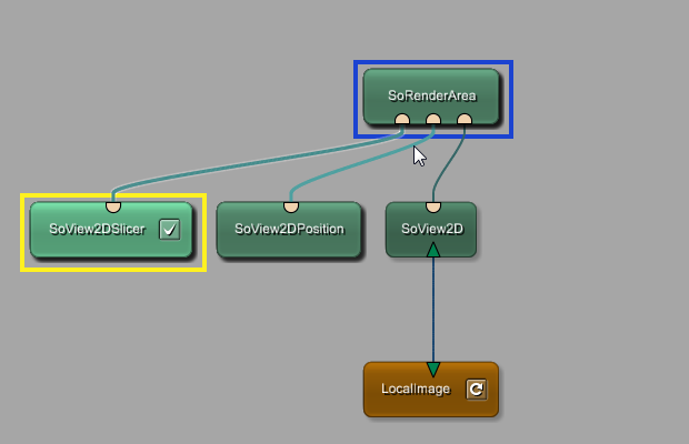
However, Open Inventor group modules have a dynamic and unlimited number of input connectors, and when not dragging to establish a connection, only the connected connectors are visible. On starting to establish a new connection, all Open Inventor group modules in a network show their otherwise hidden additional input connectors. Those additional input connectors are smaller than the regular connectors and placed to the left and to the right of the regular connectors. On connecting to an additional connector, the connection is established and the additional connector becomes a regular connector, so that for the next connection, even more additional connectors are available.
Table 3.7. Dragging a New Connection Generates New Input Connectors to the Sides of Regular Connectors

|
|
|
|
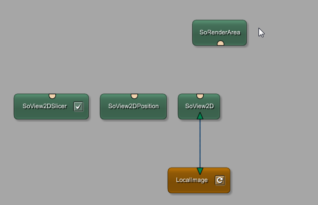
Connecting from an Open Inventor group module is basically the same as connecting to such a module.
However, new dynamic input connectors appear only if the mouse cursor is placed to the left or to the right of existing regular input connectors. Once an additional connector has appeared under the mouse cursor, it can be used for establishing a connection by clicking on it, holding the left mouse button, and dragging to an output connector.
Modules can be connected by moving their input and output connectors close to each other.
Grab a module by clicking and holding the left mouse button, then move it close to the module with which the connection should be established. If the first free, compatible connectors are close enough, a stippled preview of the module and its connection is rendered. Release the mouse button to establish the connection, and the dropped module is automatically positioned at the preview location.
The same procedure works for connecting a destination module.
![[Note]](images/note.png) | Note |
|---|---|
The stippled preview connection is always rendered in the middle of the preview module's silhouette and not at the actual position of the connector on the module. |
When connecting to an Open Inventor group by proximity and the group already has at least one input connection, all subsequent connections are generated at the first or the last dynamic connector. A new connection cannot be established by proximity between already existing connections. Use the method described in Section 3.4.1.1.1, “Connecting to Open Inventor Groups by Dragging” or Section 3.4.1.1.2, “Connecting from Open Inventor Groups by Dragging” for connecting modules in between existing connections.
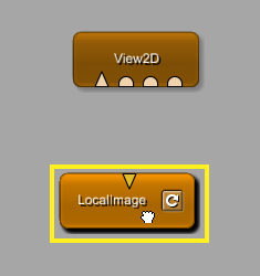
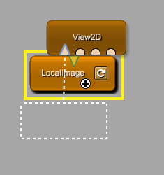
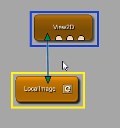
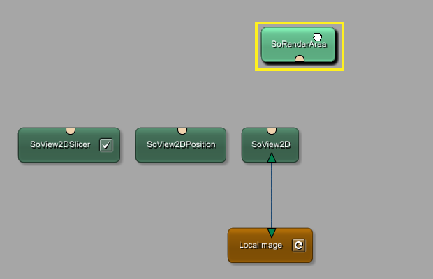
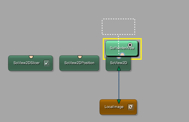
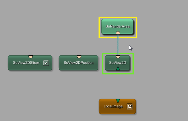
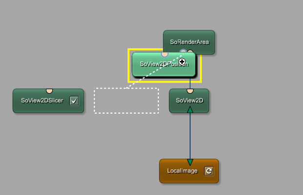
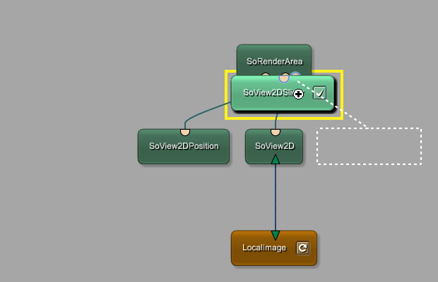
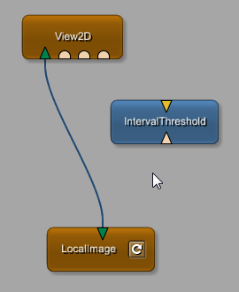
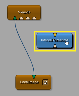
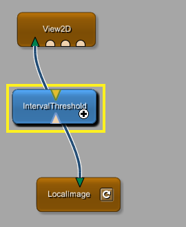
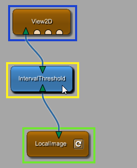
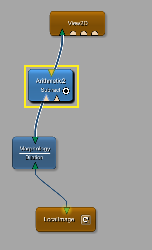
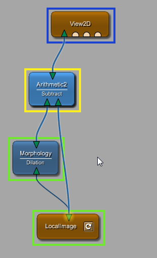
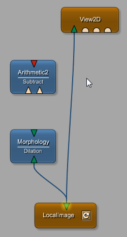
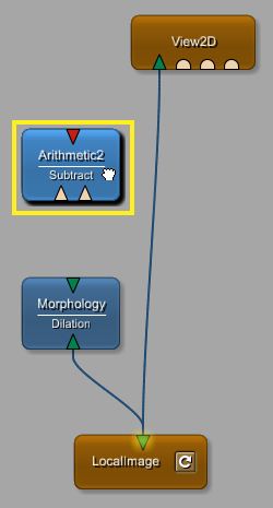
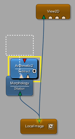
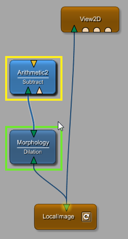
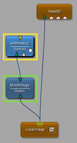
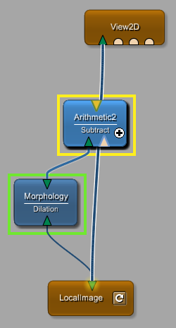
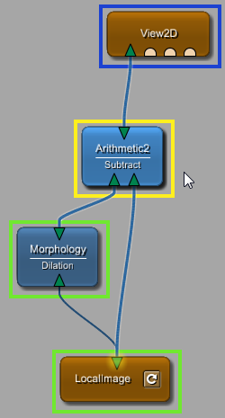
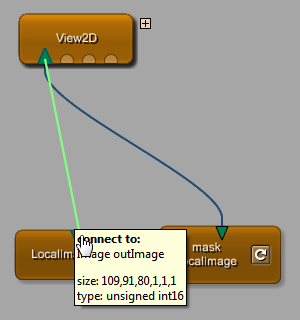
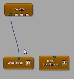
To insert a module into an existing connection, start by grabbing the module. This is done by left-clicking it and holding the mouse button while moving the mouse. Move the module over an existing connection. If the module can be inserted into the connection, the connection is highlighted, and the mouse cursor changes to a plus sign. On releasing the mouse button, the module is inserted into the connection.
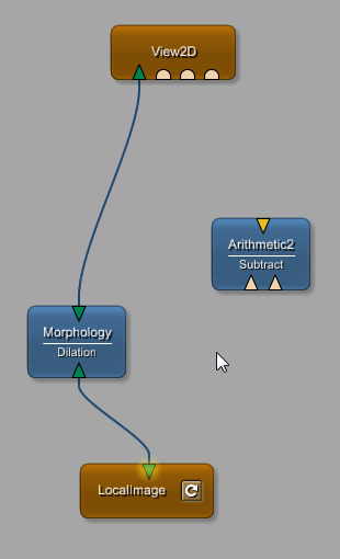
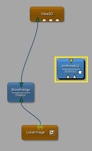
If a module has more than one input connector and is dropped onto an existing connection, the leftmost free input connector is used to establish the connection.
| Note |
|---|---|
In the following two examples, all described methods of establishing connections are mixed. |
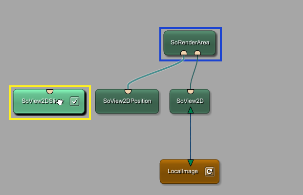
If the leftmost input connector is already connected, the first leftmost free input connector might just be the second input connector.
There are also multiple ways of disconnecting modules.
An input connection or a number of output connections can be removed by dragging a new connection to the network's background. Connections are selectable and any selected network item can be removed by pressing DEL. Connections have a context menu that offers to disconnect the selected connection, or in the case of a bundled module group connection, all connections.
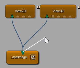
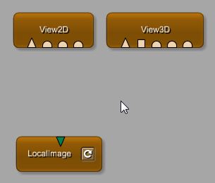
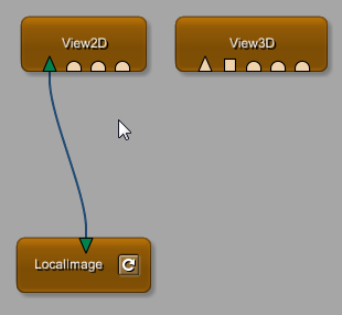
A single input connection can be removed by starting to drag a new connection from an already connected input connector and then releasing the drag over an empty region of the network.
If the drag is started on an output connector with multiple connections, and is released over the network's background, all output connections are removed.
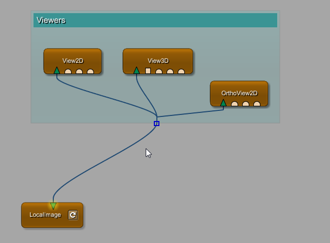
Connections can be selected by clicking on them with the mouse.
A selected connection has its own highlighting and is removable by pressing DEL.
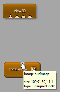
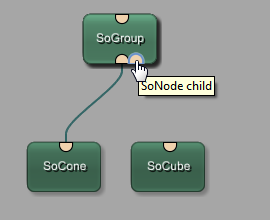
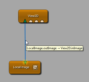
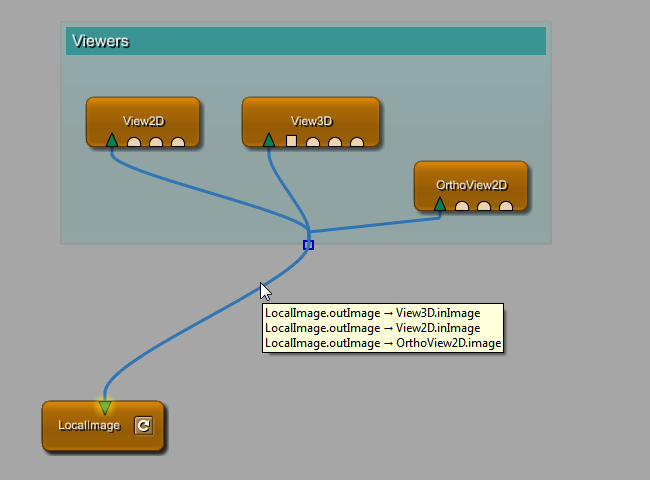
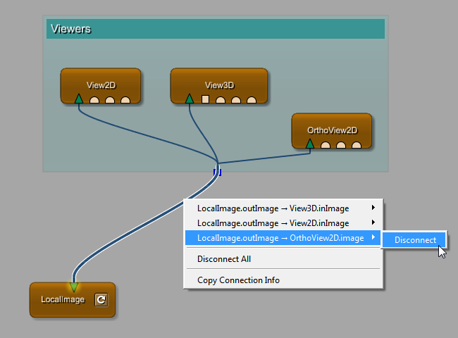
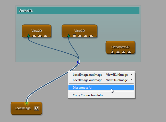
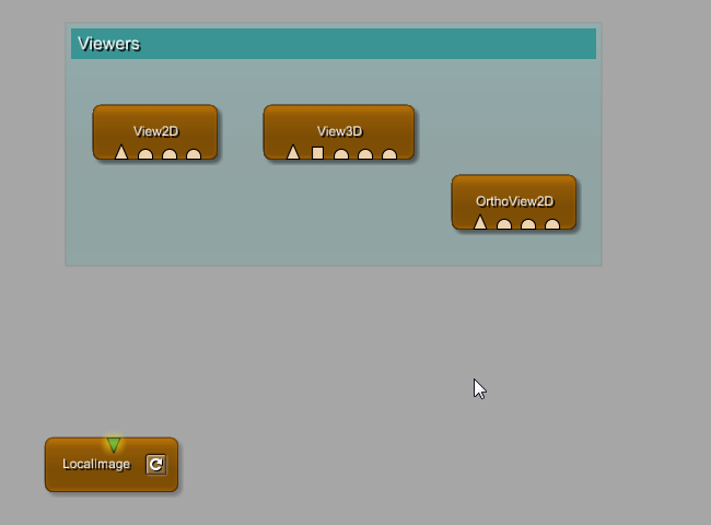
Connections not only have a tooltip showing the source and destination connector, but also a context menu where single connections or all connections, if they are bundled, can be disconnected.
The next example features a module group (see Section 3.11, “Using Groups”) to show that disconnecting by context menu also works for connection bundles.
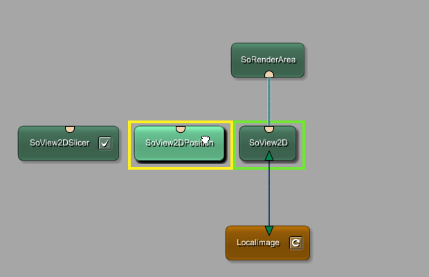
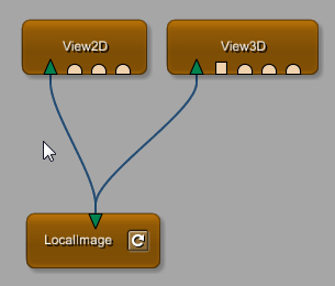
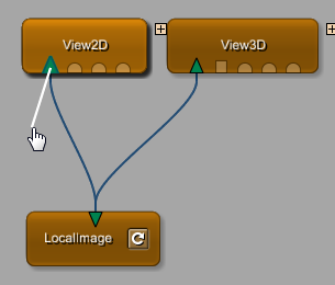
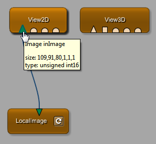
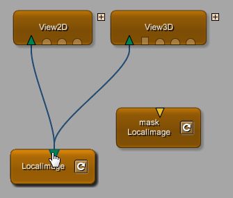
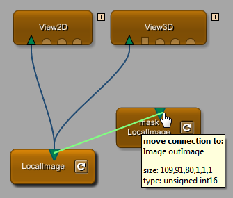
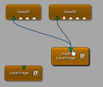
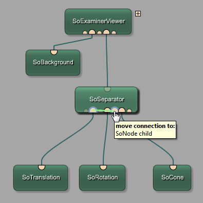
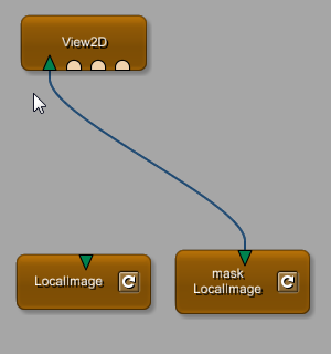
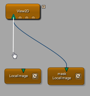
Connections can be moved from input connector to input connector, or from output connector to output connector.
The connector can be on different modules or on the same module.
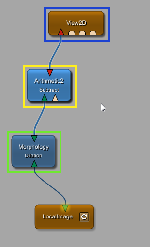
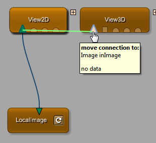
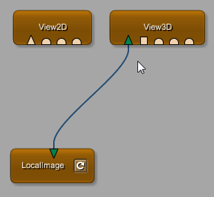
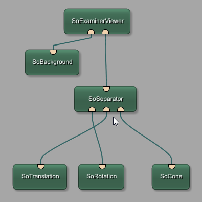
To move a connection, drag it and move it to the destination connector. If the connection is possible, the intermediate connection is rendered in green. On dropping the connection, the connection to the new connector is established.
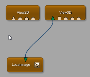
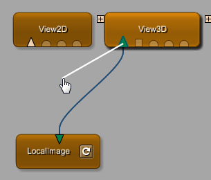
If the moving of connections takes place at an output connector, multiple connections can be moved in a single interaction.
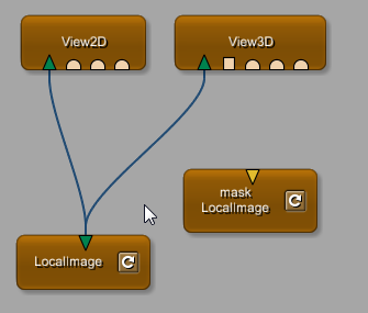
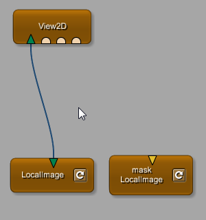
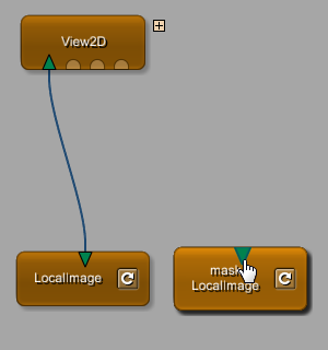
Input connections can be copied by holding CTRL+SHIFT and dragging an existing input connection to another input connector in the network.
An input connector can only be connected with a single output connector.
When connecting another output connector to an already connected input connector, the previous connection of that input connector is replaced.
Similarly, if a new connection is dragged from an already connected input connector, the previous connection is replaced by the new connection.
© 2026 MeVis Medical Solutions AG
| |  | |
| 3.3. Connector and Connection Types |  | 3.5. Mouse Pointers |