| 3.3. Connector and Connection Types | ||
|---|---|---|
 | Chapter 3. Modules and Networks |  |
| 3.3. Connector and Connection Types | ||
|---|---|---|
| | Chapter 3. Modules and Networks | |
In MeVisLab, three types of connectors are defined.
![[Note]](images/note.png) | Note |
|---|---|
In principle, every module type can have any kind of connector. |
Table 3.3. Connectors
| Look | Shape | Definition |
|---|---|---|
 | Triangle | ML images |
 | Half-circle | Open Inventor scene |
 | Square | Base objects: pointers to data structures |
ML image connectors can be set to display their state, see Section 4.3.7, “Preferences — Network Appearance”.
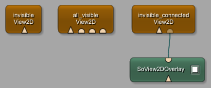
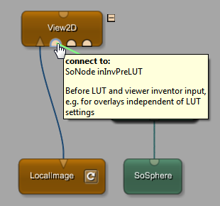
Connectors can exist in a semi-transparent design. This is the case if a connector is hidden but connected. An example for a module with Open Inventor inputs that can be hidden is the View2D module (see Section 3.9.2, “Additional Inputs”).
| Note |
|---|---|
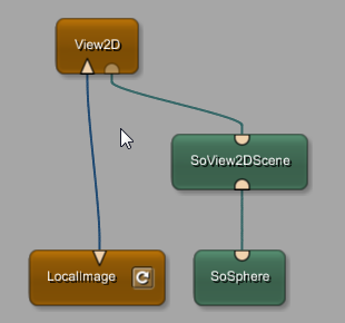
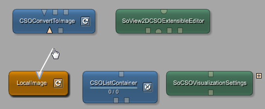
Modules with hidden input / output fields can be made to show those fields in different ways. Some modules provide the option to toggle the visibility of hidden fields in the module's context menu (e.g., View2D, View3D). Other modules might offer a field on their panel to adjust the number of shown connectors (e.g., Switch). All modules reveal their hidden input and output connectors when starting to draw a connection in the network. If a module has hidden connectors, an icon appears at the top right hand corner of such a module. When hovering with the mouse cursor over that icon while still drawing the connection, the module shows all its connectors that are interactively connectable now if the connection is compatible. On establishing the connection, all other hidden connector disappear again. On pressing SPACE, the network is rendered in a special information mode where also all invisible connectors are revealed. Pressing CTRL+SPACE shows invisible connectors only. To toggle back to the normal view press SPACE again. |
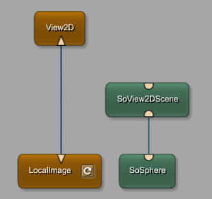
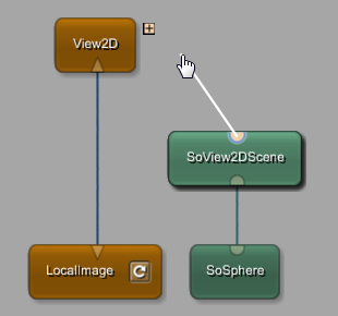
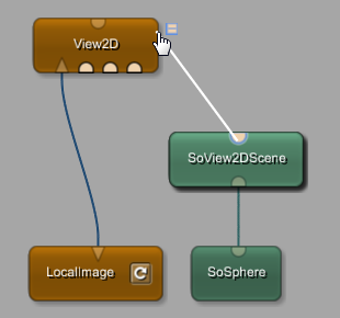
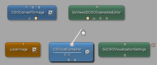
To connect to an otherwise invisible connector, start dragging from a source connector. Once the drag has started, modules with invisible connectors will display a plus sign in their upper right corner. Move the dragged connection over this plus sign to reveal the hidden connectors of that module. The connection can then be established by dropping it on the desired destination connector.
In a MeVisLab network, we distinguish between a data connection and a parameter connection.
A data connection connects modules by their input/output connectors. Those connections carry ML mages, Open Inventor scene objects, or general Base objects.
A parameter connection connects fields of modules. Such a connection can also connect fields of the same module with each other.
Table 3.5. Connections
| Type | Look | Characteristics |
|---|---|---|
| Data connections (connector connections) |  | The direct connection between connectors. Depending on which connectors are involved, the connection is rendered in a different color: blue for ML, green for Open Inventor, brown for Base. |
| Parameter connections (field connections) |  | Connections created by connecting parameter fields within or between modules. For more information, see Section 3.10.2, “Connections Context Menus”. |
Data connections are established, for example, by clicking on a connector and drawing the connection to another connector. Only connectors of the same type can be connected.
| Note |
|---|---|
Refer to Section 3.4, “Connecting, Disconnecting, Moving, Copying, and Replacing Connections” for more detailed information on different methods to connect and to disconnect modules. |
When interactively connecting Base fields, an internal type system checks whether the particular Base connection is possible.
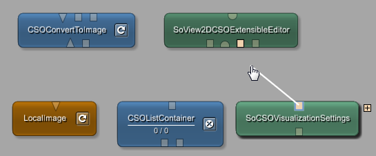
MeVisLab checks the data types of all available connectors while drawing a connection. Incompatible connectors are rendered in a faded-out style, while compatible connectors remain clearly visible.
| Note |
|---|---|
Base connectors can have different data types; connecting these incompatible connectors is possible only via scripting and results in the connection being drawn in red. For more information on Base connectors, see the Getting Started, chapter “A Note on Base Types Checks”. |
Parameter connections are established similarly by clicking on a field on a panel and drawing the connection to another field (on the same panel or another one). For details on parameter connections, see the Getting Started, chapter “Parameter Connection for Synchronization”.
Parameter connections can be moved between fields by clicking on the connected connector/field and pressing SHIFT while dragging it to another field. The other connected fields will be updated accordingly.
Parameter connections can be copied, similar to moving them, by holding CTRL+SHIFT. Ensure that the option Debug Widgets is disabled (see Section 4.6.9, “Debug Widgets”).
![[Tip]](images/tip.png) | Tip |
|---|---|
To abort the interactive establishing and removing of connections between modules (and the horizontal moving of connections), press ESC. Alternatively, abort the process by either drawing the connection to a connector of the wrong type (displayed in red) or by returning it to the output connector. The new connection will not be drawn, and no existing connections will be removed. |
© 2026 MeVis Medical Solutions AG
| |  | |
| 3.2. Module Network Panels |  | 3.4. Connecting, Disconnecting, Moving, Copying, and Replacing Connections |