| 4.3. Parameter Connection for Synchronization | ||
|---|---|---|
 | Chapter 4. Implementing a Contour Filter |  |
| 4.3. Parameter Connection for Synchronization | ||
|---|---|---|
| | Chapter 4. Implementing a Contour Filter | |
Besides data connections between module inputs and outputs (Image, Inventor, and Base connectors) it is also possible to connect module fields via a parameter connection. The values of connected fields are synchronized, that means when changing the value of one field, all fields connected to this field will be adapted to the same value.
Some important points:
Fields can be connected to an arbitrary number of other fields as source, but only once as destination. (Similar to data connections, for which an output connector can be connected to an arbitrary number of other connectors but an input connector can only be connected once.)
Connections between fields may be unidirectional or bidirectional.
Unidirectional: Field A is the output and field B the input. Changes in field A reflect in field B but changes in field B have no effect on field A.
Bidirectional: Field A is the output and field B the input and vice versa (two parameter connections). Changes in field A reflect in field B and changes in field B reflect in field A. (This is the setting we will use in our example.)
![[Note]](images/note.png) | Note |
|---|---|
MeVisLab prevents the creation of infinite loops between fields in most cases.
A notable exception is a loop between Inventor fields when ML or macro interface fields
constitute intermediate fields. In this case the loop cannot be detected and - once
triggered - will lead to a background computational load. This can be avoided by using
the |
Not all connections between all fields are sensible. Usually the connected fields should be of the same type.
Parameter connections may be established both between fields within the same module and between fields of different modules.
On the MeVisLab user interface, parameter connections are established by dragging fields onto the labels of automatic panels (and most scripted MDL panels, see the MeVisLab Reference Manual, chapter “Parameter Connections Inspector” for details).
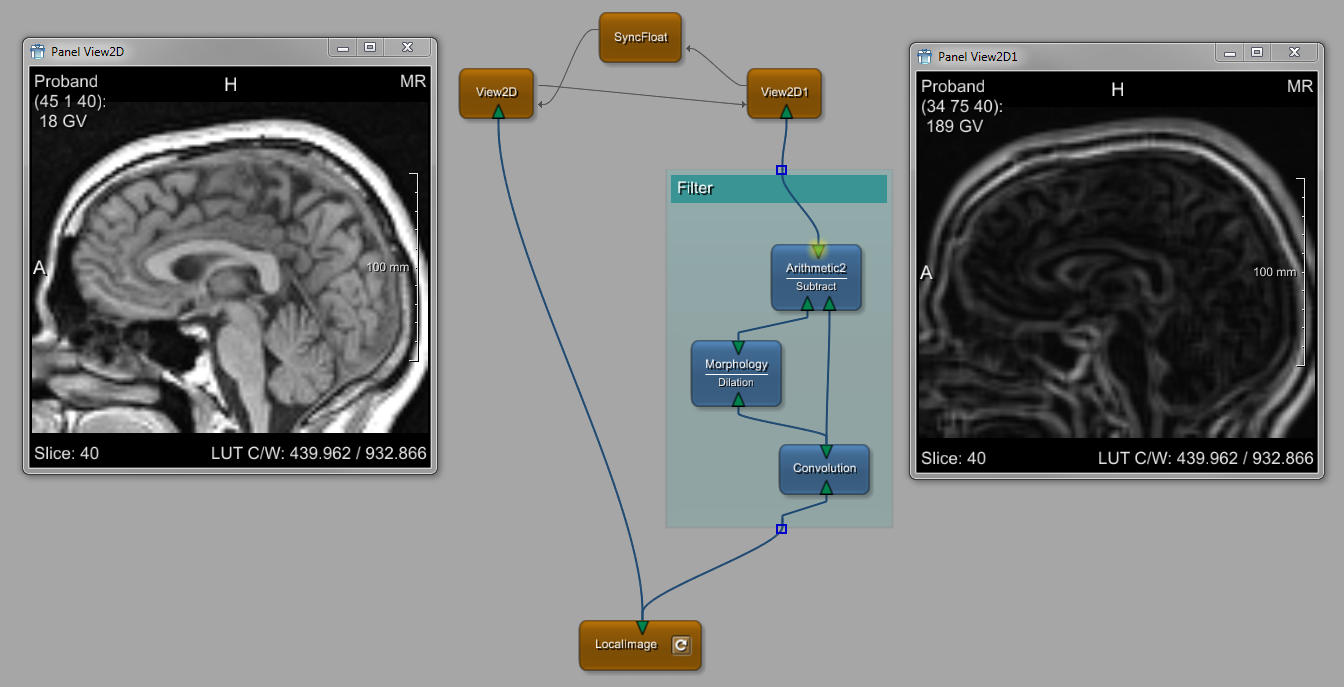
In our example, a bidirectional parameter connection is the way to
synchronize the View2D modules so that
the same slice is rendered in both viewers. To establish this, proceed as
follows:
Add a SyncFloat module to the network
and open its panel with a double-click.
Right-click each View2D module
to open the context menu and select
Show Window → Automatic Panel
(alternatively, press ALT and double-click the module).
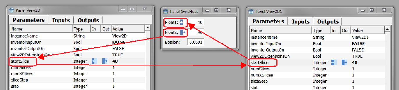
The field that controls the currently rendered slice
in a SoView2D module is the
startSlice field.
On the SoView2D panel, select
the label of the startSlice field and
drag the (invisible) connection onto the label of startSlice field on the SoView2D1 panel. The connection is drawn as
thin gray arrow with the arrowhead pointing to the module that
receives the parameter as input.
In the other direction drag the startSlice
field from the SoView2D1 panel to the
float1 field of the SyncFloat
panel, and from the same panel the float2 field
to the startSlice field of the
SoView2D panel. The intermediate
SyncFloat module breaks the inevitable notification loop
by only triggering the second connection at real value changes.
![[Tip]](images/tip.png) | Tip |
|---|---|
Another typical way of notating the fields is
“InstanceName.FieldName”, for example |
As a result, moving through the slices with the mouse wheel (“slicing”) in one of the viewers synchronizes the rendered slice in the second viewer.
| Tip |
|---|---|
A list of all parameter connections is displayed in the Parameter Connections Inspector View (which can be opened via the menu bar, View → Views → Parameter Connections Inspector). Right-click the connections for a context menu with various options. |
For further information on parameter connections, please refer to the MeVisLab Reference Manual.
This is the end of this example. The full network is delivered with the demos of MeVisLab (available via Help → Welcome → more... → ContourFilter.mlab).
© 2026 MeVis Medical Solutions AG
| |  | |
| 4.2. Implementing the Contour Filter |  | Chapter 5. Defining a Region of Interest (ROI) |