| 3.9. Module Handling | ||
|---|---|---|
 | Chapter 3. Modules and Networks |  |
| 3.9. Module Handling | ||
|---|---|---|
| | Chapter 3. Modules and Networks | |
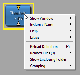
Right-click modules to open the module context menu. Its contents slightly depend on the module type. Available groups of entries:
Open Inventor only: Section 28.7, “Set Open Inventor Override Flag (Inventor Modules)”
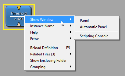
Each module has at least one panel: the automatic panel, which lists all fields and parameters of the module. Use it for an overview or for editing the parameters (see also Section 11.1, “Fields”).
![[Tip]](images/tip.png) | Tip |
|---|---|
Refer to chapter Section 4.3.10, “Preferences — Shortcuts” for a shortcut for opening a module's automatic panel. |
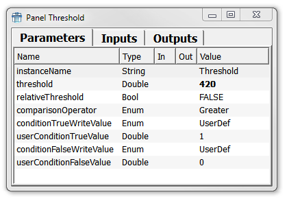
The automatic panel lists all fields of the module in order of their initialization in the C++ code or of their definition in the Macro definition. It also shows the data type of the field, whether it is an input or output field, and its current value. The value can be edited directly on the automatic panel.
If a field has a value different from the default value of the field for that module, the Flags column will have a ! entry. You can sort by the Flags column to see all fields with a changed value more easily.
| Tip |
|---|---|
The header of the list of fields of the automatic panel has a context menu where you can toggle how to sort the fields or to turn off the sorting at all. In the later case, the fields are ordered as they are implemented in C++ or in the script. |
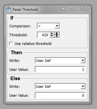
Typically, another type of panel is also available, which displays the parameter fields in a structured layout and is written in MDL.
Important points:
It is possible to add fields that are not in the C++ code.
It is possible to add field listeners that can trigger script code.
It is possible to exclude rarely used fields from the structured panel. This way, the panel's usability might be enhanced. (Fields can always be edited in the automatic panel.)
Other windows may be available. For example, for the View2D module, a Viewer and a Settings window are available. For information on defining windows, see the MDL Reference, chapter “1.3.2.1. Window”. For an example, see the Getting Started, chapter “Adding the Macro Parameters and Panel”.
Show Scripting Console
Opens the Scripting Console with the context of the current module, allowing, for example, ctx.field("fieldName") calls to reference and access fields belonging to that module, see Section 4.7.1, “Show Scripting Console”.
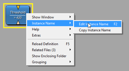
Edit Instance Name
This option allows distinguishing between several instances of the same module. Within a network, each module instance must have a unique name. If no specific instance name is provided, copies of the modules are automatically numbered (1, 2, 3, etc.). Alternatively, the instance can be renamed manually.
![[Note]](images/note.png) | Note |
|---|---|
Instances of modules have to be unique because modules are addressed by their instance names in scripting. |
Select the option or use the respective shortcut (see Section 4.3.10, “Preferences — Shortcuts”) to open a dialog for entering a new instance name.
The instance name is displayed above the module name. If the instance name is the module name plus a number, only the instance name is displayed, as it already includes the module name.
Copy Instance Name
This option copies the module's instance name to the system's clipboard. This can, for example, be used to copy the module's name into scripting code.
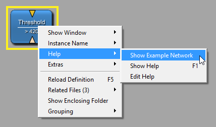
Show Example Network
Opens the example network in a new network tab. This option is only active if an example network exists (otherwise, the entry is grayed out).
If a module has multiple example networks, this entry is a menu item, displaying the number of example networks. Upon selection, a submenu offers all available example networks by their names.
Show Help
Displays the HTML help file for the module in the default browser. This option is only active if a help file exists.
Edit Help
Edits the mhelp file in MATE. Use this option if fields have changed (renamed, new, or removed) or if the module is new. This creates the initial mhelp file if it does not exist or refreshes an existing mhelp file with updated field information.
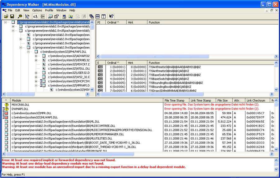
Show DLL Dependency (not on macro modules)
This option uses (on Windows) the Dependency Walker for checking and displaying all dependencies for the module. For more information, please refer to the help of the Dependency Walker. Linux has its own solution for displaying similar information.
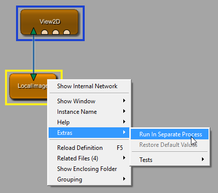
Run In Separate Process (not on Open Inventor modules)
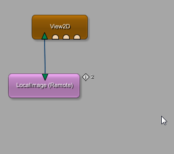
MeVisLab allows for running ML and macro modules in background processes, so-called worker processes. We call the underlying concept Remote Modules. “Run In Separate Process” will replace the selected module in the network by a remote module and start a MeVisLab worker process that loads the replaced module. Field and image changes are transmitted asynchronously between MeVisLab and the worker process.
Remote Modules offer an alternative approach to multithreading for utilizing multiple CPUs and enabling asynchronous processing. For example, a remote module can be used to move long-running calculations into the background to keep the GUI responsive.
| Note |
|---|---|
Restrictions:
|
Restore Default Values
Resets all fields whose values differ from their default value back to the default value. (These are the fields with an ! entry in the Flags column in the automatic panel.)
Set Open Inventor Override Flag (only on Open Inventor modules)
See Section 28.7, “Set Open Inventor Override Flag (Inventor Modules)”.
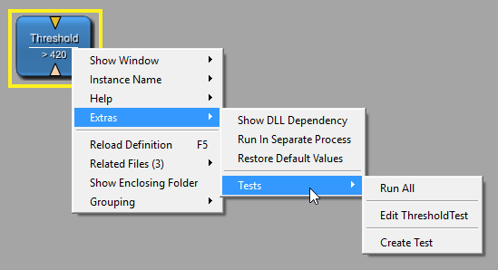
Tests
In the Tests submenu, testing options are available.
Run All
Starts all available tests for the module. In the case of Threshold, the generic test case “Formal” and the “Functional” test case are executed. When the tests are finished, a test report window is opened. (See also Section 4.6.5, “Run Module Tests...”, the TestCenter Reference, and the Getting Started, chapter 16, “Using the TestCenter”.)
Edit <AssociatedTest>
Opens the files of a test associated with the selected module.
Create Tests
Opens the TestCaseManager on the tab to create a new functional test.
Reloads the module's definition (.script and optional .py file). This is necessary when laying out panels and windows, or when working on the scripting.
| Tip |
|---|---|
A single selected module can also be reloaded by pressing the according shortcut key for the OS. Refer to Section 4.3.10, “Preferences — Shortcuts”. |
If modules are being reloaded, an animation (modules turn white and slowing gain their color back) indicates that the modules' definitions have indeed been reloaded.
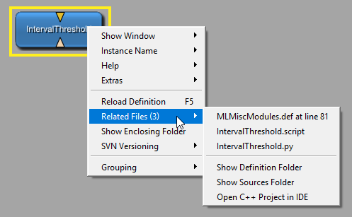
Related Files: Lists all files belonging to the module. Possible file types are .def/.script (MDL definition files), and .py (Python scripting files). Select a file to open it in the default editor (as set in Section 4.3.4, “Preferences —
Supportive Programs”).
Show Definition Folder: Opens the definition folder of the module that contains the .def and .script files. If the module is augmented by scripting, the .py files can also be found there.
Show Sources Folder: Opens the folder containing the module's source code files, if available. Otherwise, the option is grayed out.
Shows the directory where the definition file of the module is located.
For the Groups functions, see Section 3.11, “Using Groups”.
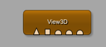
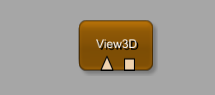
Modules may have more inputs and outputs than are initially visible, to keep the module display as uncluttered as possible. An example for a module with possibly hidden inputs is the View3D module. It offers the additional context menu entry View3D Options → Show Inventor Inputs. If enabled (which is the default), three Open Inventor input fields are displayed. The option can also be toggled in the module's Settings panel.
| Tip |
|---|---|
The three Open Inventor inputs of |
Depending on the programming, the number of inputs may be dynamically set. For example, this is the case for the Switch module.
For a supporting visualization while interactively drawing connections, see Section 3.3, “Connector and Connection Types”
In the context menu of macro modules, the option Show Internal Network is available. If selected, the network of the macro is opened in a separate network tab.
| Tip |
|---|---|
Refer to chapter Section 4.3.10, “Preferences — Shortcuts” for a shortcut to open a macro's internal network. |
| Note |
|---|---|
Showing the internal network of a macro this way shows the live network; this means that all fields of all modules will have the value at the moment of opening the network, and changing field values in this network will change the state of the macro. If you change the network and save it, all the changed fields will be saved for that macro as well. If you want to work on an internal network of a macro, open its network with the option “Related Files” from the macro's context menu and select the corresponding |
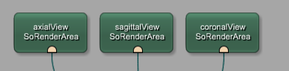
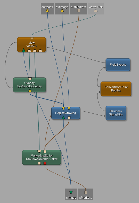
The pseudo-connectors shaded in gray are placeholders and indicate the input (bottom) and output (top) parameters of the macro, which constitute the connectors of the macro module. They are automatically drawn at the edges of the bounding box of the network. Important points about them:
They cannot be moved or removed interactively but can only be changed in the script.
They cannot be selected in a rectangle but each of them can be clicked, in which case the input/output square, the connection(s), and the connected module(s) are highlighted.
| Note |
|---|---|
Modules in an internal network of a macro that are connected to the macro's input / output fields (visualized by being connected to the pseudo-connectors) cannot be removed interactively from the network. On an attempt to remove such a module, a window with a warning pops up. If such a module needs to be removed, the corresponding connection must first be removed in the scripting, and then the macro needs to be reloaded. |
| Note |
|---|---|
The tab of the internal network remains connected to the module from which it was opened. When the module is deleted or its containing network is closed, the tab with the internal network is also closed. |
© 2026 MeVis Medical Solutions AG
| |  | |
| 3.8. Module Highlighting |  | 3.10. Network Handling |