| 10.2. Adding the Macro Parameters and Panel | ||
|---|---|---|
 | Chapter 10. Developing a Macro Module for an Applicator |  |
| 10.2. Adding the Macro Parameters and Panel | ||
|---|---|---|
| | Chapter 10. Developing a Macro Module for an Applicator | |
So far, the macro module has no points of interaction. Therefore, the input/output, the parameters/fields and the scripting need to be added.
To edit the panel and its underlying scripting, right-click the
ApplicatorMacro module and select
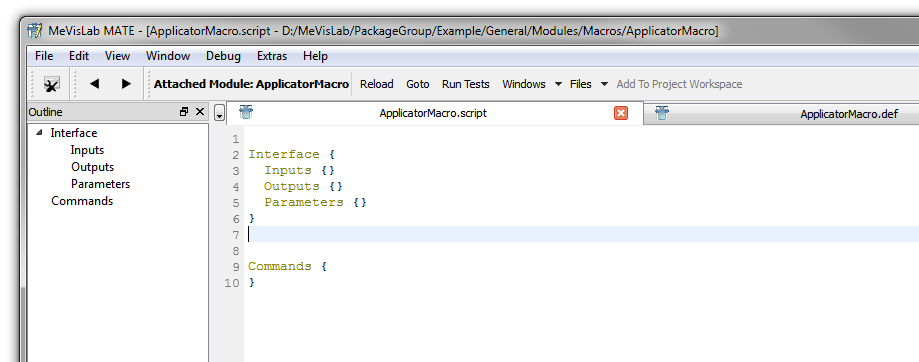
Related Files → ApplicatorMacro.script to open the file in the in-built text editor MATE.
Since we just defined this macro module, the script file is basically
empty except for some placeholders.
![[Tip]](images/tip.png) | Tip |
|---|---|
MATE comes with some special features like autocompletion, syntax highlighting, indentation, etc. for MDL, Python and help files. For an extensive list, see the MeVisLab Reference Manual, chapter “MATE”. |
We want three sections in the .script
file:
Interface: defines the inputs and outputs of
data connections for the macro. In our case, the macro has no
inputs from other modules, but one output which is the Inventor
scene.
Commands: defines the scripting file to be
executed upon the activity of defined fields.
Window: defines the panel of the macro to set
the parameters. In our case, length and diameter. This is an
optional entry; if not defined, only the automatic panel is
available.
![[Note]](images/note.png) | Note |
|---|---|
The window section of the GUI could also be implemented in the
|
First we will define the interface. As no inputs are needed,
keep this line as it is. For the output, we address the output of the
SoGroup module named Applicator. The following lines will
result in an output field that will "deliver" the applicator.
Interface {
  Inputs = ""
  Outputs {
      Field Scene { internalName = "Applicator.self" }
  }
  Parameters = ""
}
Enter the lines in MATE and save the script file.
Then reload the module by right-clicking the macro module and
selecting Reload Definition to apply the
changes. The ApplicatorMacro module
now shows an Open Inventor output connector.
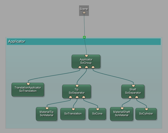
The internal network of the macro shows the output placeholder. In the mouse-over, the output field name is displayed.
As next step, we will define the parameters for our interface. In this example, we want to have two parameters:
length: this shall be the overall length of the
applicator.
diameter: this shall be the diameter of the
applicator.
These two parameters need to be added to the
Interface part of the script file. Besides setting the
parameter type (type) and the default value
(value), you can also add a minimum and a maximum value
to limit the range to sensible values.
Interface {
  Inputs = ""
  Outputs {
    Field Scene { internalName = "Applicator.self" }
  }

  Parameters {
    Field length {
      type  = float
      value = 20
      min   =  1
      max   = 50
    }
    Field diameter {
      type  = float
      value =  3
      min   =  0.1
      max   = 10
    }
  }
}
Once again, save the script and reload the macro module.
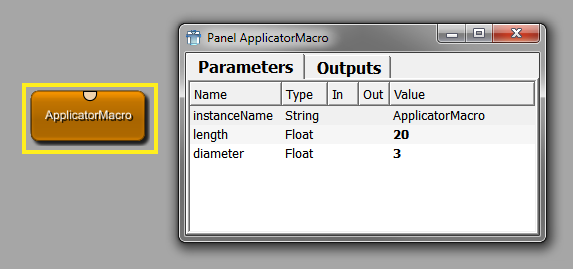
Open the automatic panel, either by double-clicking the module, by holding ALT and double-clicking the module, or by right-clicking the module and selecting Show Window → Automatic Panel from the context menu. The new parameters are visible in the automatic panel. They can also be edited there by clicking on each value field and editing the value.
In principle, this would be enough to enter the values. However, usually a more user-friendly panel should be offered. In the panel, values can be sorted by correlation or importance and distributed on various tabs. It is also possible to leave rarely used parameters out of the panel to make it slimmer; as the automatic panel of a module is always available, the user can always view and edit all parameters there.
To create a panel for the two parameters, the new section
Window is added at the end of the script file. Besides
defining the fields in Category, you can also add a step
value which will regulate how large the step is when moving through
the values with the spin box arrows or the mouse wheel (with the mouse
cursor over the field). As the diameter is smaller than the length, it
makes sense to set a smaller step size here.
Interface {
  Inputs = ""
  Outputs {
    Field Scene { internalName = "Applicator.self" }
  }

  Parameters {
    Field length {
      type  = float
      value = 20
      min   =  1
      max   = 50
    }
    Field diameter {
      type  = float
      value =  3
      min   =  0.1
      max   = 10
    }
  }
}

Commands {

}


Window {
  Category {
    Field length   { step = 1   }
    Field diameter { step = 0.1 }
  }
}
Save the script and reload the macro module.
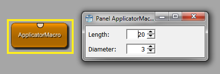
Now open the panel, either by double-clicking the module (because the panel is the new default panel) or by right-clicking the module and selecting Show Window → Panel from the context menu. The new parameters are visible in the panel and can be edited manually (or by using the spin arrows or the mouse wheel).
All parameters are defined and the panel is ready for entering
values — however, we still do not have any interaction. So the last
section Command needs to be added, in which the
respective scripting file (a Python file) and the fields
this scripting file should “look at” need to be
entered
The source will be a local file which we will add manually, with
the name ApplicatorMacro.py by convention.
To relate to the scripting, we need two field listeners that
listen to fields and call the script command given in the
command tag when the field changes. The functions
AdjustLength and AdjustDiameter used in the
code do not exist yet but will be defined by us in the Python
file.
Interface {
  Inputs = ""
  Outputs {
    Field Scene { internalName = "Applicator.self" }
  }

  Parameters {
    Field length {
      type  = float
      value = 20
      min   =  1
      max   = 50
    }
    Field diameter {
      type  = float
      value =  3
      min   =  0.1
      max   = 10
    }
  }
}

Commands {
  source = $(LOCAL)/ApplicatorMacro.py

  FieldListener  length   { command = AdjustLength   }
  FieldListener  diameter { command = AdjustDiameter }
}

Window {
  Category {
    Field length   { step = 1   }
    Field diameter { step = 0.1 }
  }
}
Save the script and reload the macro module. If the Python file or the scripting commands do not exist yet, errors messages will appear in the Debug Output of MATE. Do not be concerned — we will add everything we need for real interactivity in the next section.
| Tip |
|---|---|
Panels can have a more complex design; for the possibilities, see the MDL Reference and the MDL panel example modules in MeVisLab (search for modules starting with “Test...”). |
© 2026 MeVis Medical Solutions AG
| |  | |
| Chapter 10. Developing a Macro Module for an Applicator |  | 10.3. Programming the Python Script |