| 7.3. Creating the Interaction | ||
|---|---|---|
 | Chapter 7. Creating an Open Inventor Scene |  |
| 7.3. Creating the Interaction | ||
|---|---|---|
| | Chapter 7. Creating an Open Inventor Scene | |
Although the applicator created in the last section is complete, it is not yet functional so that you can easily point the tip to a position. For this, some interactivity must be enabled.
The first module necessary for this is SoCenterballManip. In the Inventor Reference, the following information can be found for this module:
“SoCenterballManip is derived from SoTransform (by way of SoTransformManip). When its fields change, nodes following it in the scene graph rotate, scale, and/or translate. [...] On screen, this manipulator will surround the objects influenced by its motion. This is because it turns on the surroundScale part of the dragger. ”
![[Note]](images/note.png) | Note |
|---|---|
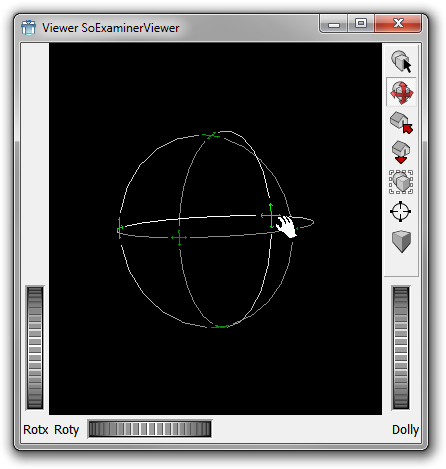
When attaching the SoCenterballManip the first time, it might appear very small in the viewer. Just click on it to trigger a rescaling. Once rescaled, the manipulator will keep its size. |
This means that once we put an object in the middle of the sphere opened by this module, it can be moved around with it.
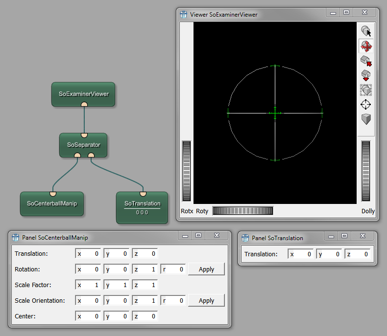
To keep the interaction separate from the applicator, add another separator.
Then add the modules SoCenterballManip and SoTranslation. The translation module is necessary to position the centerball (as the latter is foremost intended for rotation and not perfect for translation).
To see the actual ball, use the mouse to rotate the view.
![[Tip]](images/tip.png) | Tip |
|---|---|
Press the ALT button to toggle between the view mode (for navigation) and the pick mode (for interaction, changes the data on the panel of |
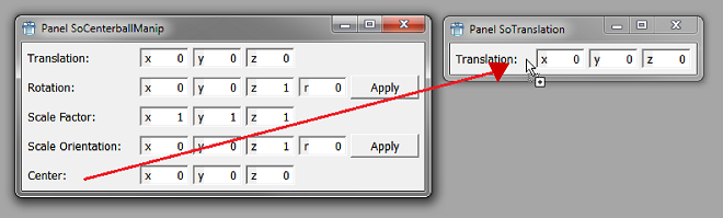
To connect the translation of the modules, a parameter connection has to be established between the Center field of SoCenterballManip and the Translation field of SoTranslation. This is done by opening the panels, clicking near the Center field and dragging it onto the other panel until a little plus sign appears. The parameter connection is drawn as a thin line between the modules, always starting at the modules' side (never on top or bottom, like data connections do).
| Tip |
|---|---|
For an overview of all parameter connections, open the Parameter Connections Inspector via the menu bar, View → Views → Parameter Connection Inspector. |
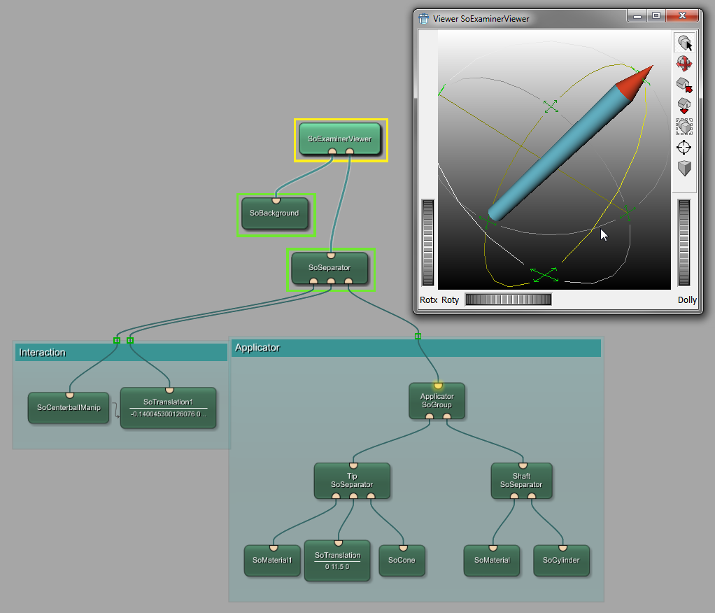
Now we can combine the interaction part and the applicator. For this, connect the applicator to the second separator.
The applicator can now be rotated or dragged into any direction by using the handles on the manipulation sphere.
© 2026 MeVis Medical Solutions AG
| |  | |
| 7.2. Creating the Applicator |  | 7.4. Creating the Anatomical Image |