| 3.4. Adding Viewers to ImageLoad | ||
|---|---|---|
 | Chapter 3. Loading and Viewing Images |  |
| 3.4. Adding Viewers to ImageLoad | ||
|---|---|---|
| | Chapter 3. Loading and Viewing Images | |
Instead of using the Output Inspector
(whose display might change with every clicked connector), it is sensible
to add a viewer to the network. There are two standard macro modules
available in MeVisLab which provide standard
viewer configurations for 2D and 3D rendering, namely View2D and View3D. Especially the 2D Viewer is frequently
used to examine image processing results within a module pipeline, for
example. Once you begin to implement your own applications, you are free
to create your own viewer implementations adapted to your special
tasks.
Add a View2D module to your
network. In the Modules menu it is
located at Modules → Visualization → 2D Viewers → View2D.
The View2D module has one
input connector for the image to be rendered, as well as three
Inventor inputs.
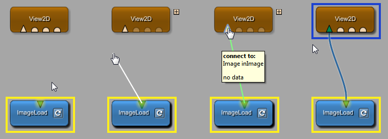
Feed in the image by connecting the image output of the
ImageLoad module with the image
input of the View2D module. This is
done as follows:
Click the output connector of ImageLoad.
Keep the left mouse button pressed while dragging the
connection to the input connector of View2D (white line).
Check that the connection is well-defined (green line).
At the input connector of View2D, release the mouse button and
establish the connection (blue line).
![[Tip]](images/tip.png) | Tip |
|---|---|
There are many more ways to connect and to disconnect modules, see Section 3.4, “Connecting, Disconnecting, Moving, Copying, and Replacing Connections”. |
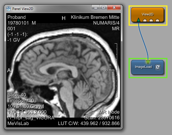
Although the connection is established, no image rendering has
started yet. To initialize rendering, open the View2D panel by double-clicking the View2D module in your network. As you can
see, the default panel is the viewer itself.
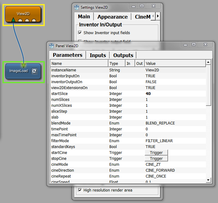
The View2D panel provides a standard viewer with many
features, like slicing, zooming, windowing, annotations, slab view,
cine mode, and many more. A full description of all supported
features and how to use them can be found on the View2D help page which you can open from the
module's context menu.
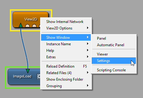
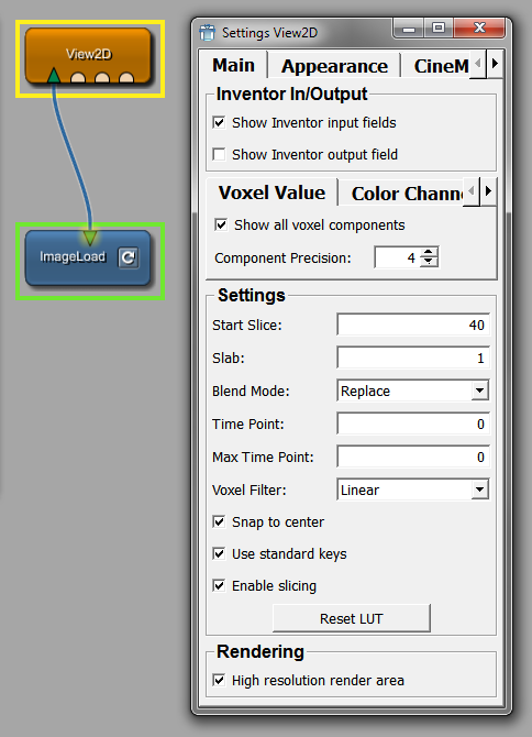
The View2D module offers
various settings. As the default panel is the viewer, the Settings
panel needs to be opened explicitly from the context menu via
Show Window → Settings.
![[Note]](images/note.png) | Note |
|---|---|
A module always has one automatic panel and may have an
arbitrary number of additional panel windows, as defined in an MDL
file (in the |
Now is a good time to save your network as MyFirstNetwork.mlab. You can do this in
several ways:
Select File → Save or press the respective keyboard shortcut (for how to get a list of all shortcuts, see the MeVisLab Reference Manual, chapter “Shortcuts”).
Click the disk symbol in the toolbar.
The network modules and all module parameters are stored. Next
time you open the network, you will get access to the loaded image
at the output of the ImageLoad
module immediately.
| Tip |
|---|---|
You can quickly re-open the last twenty networks via the menu bar, File → Recent Files. |
| Tip |
|---|---|
The most recent network file can be opened via File → Open Most Recent File which has an own keyboard shortcut. |
| Tip |
|---|---|
If the option Auto save MeVisLab
documents in the Preferences is selected, MeVisLab
networks are auto-saved as
|
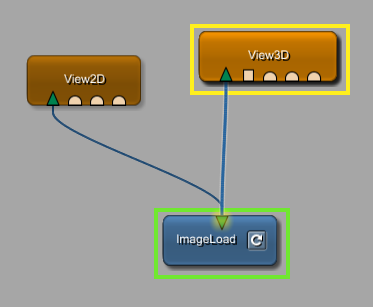
The View3D macro module is an
easy-to-use application of the SoGVRVolumeRenderer module, which is a high-end,
hardware-based image rendering module using 3D textures. Adding the
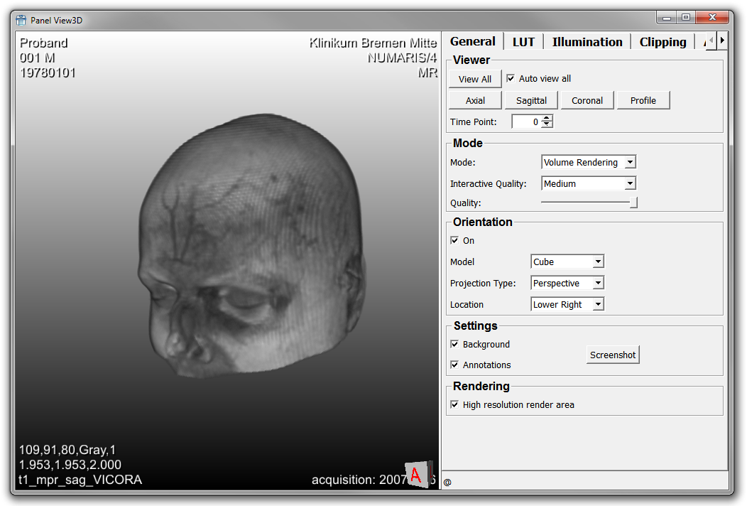
View3D module to the network, we get
access to a 3D scene of our example image.
In addition to the 3D display offered by the Output Inspector, the View3D viewer comes with several panels on which you can set display details or even record a movie.
© 2026 MeVis Medical Solutions AG
| |  | |
| 3.3. Using the ImageLoad Module |  | 3.5. Alternative Ways to Load Images |