15.3. Developing the SoBaseReceiver Module | ||
|---|---|---|
 | Chapter 15. Developing a Base Communication |  |
15.3. Developing the SoBaseReceiver Module | ||
|---|---|---|
| | Chapter 15. Developing a Base Communication | |
In this section, we will develop the Open Inventor module that is necessary to display the output of MLBaseOwner.
Technically, this module receives the Base object and constructs a simple Open Inventor scene internally on base of the parameter and attribute values in the received Base object.
![[Tip]](images/tip.png) | Tip |
|---|---|
For information on Open Inventor, see the Inventor Modules Help (for an introduction on Open Inventor and module-related help) and the Inventor Reference (converted from the original man pages). |
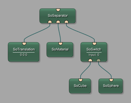
The internal scene graph of this module could also be built as a network in MeVisLab:
As you can see, SoBaseReceiver is essentially an Open Inventor separator module which has the advantage that it comes with its own viewer. The other modules deliver the translation, the color and the actual shape.
First of all, make sure that you have a user package defined as described in Section 8.2, “Creating a User Package for Your Project” or create it now.
Then run the Project Wizard and select the link Inventor Module. On the dialog Module Properties, enter the following:
Name: (So)BaseReceiver
Comment: Module renders an Inventor scene that is parameterized by a BaseOwner module.
Keyword: Example
See Also: BaseOwner
Target Package: your package, for example “Example/General”
Project: BaseReceiver (“So” is added automatically)
Click Next to proceed.
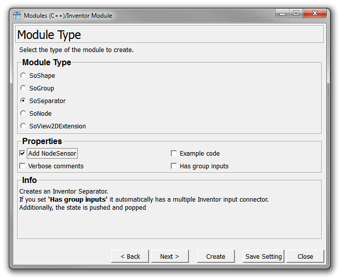
On the dialog Module Type, select SoSeparator and check the option Add Node Sensor.
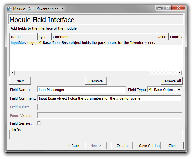
On the dialog Module Field Interface, enter one field:
Field Name: inputMessenger
Field Type: ML Base Object
Field Comment: Input Base object holds the parameters for the Inventor scene.
| Tip |
|---|---|
Why using a node sensor instead of a field sensor? In our example, it would make no difference as we only have one input field. Usually, however, there will be more than one field, and as each field sensor will add redundant code to the module, using a node sensor that will react to any changes of the Open Inventor node is usually recommended. |
Click Create to create the module.
In the default file browser of your system, two folders are opened:
folder with the source code: {packagePath}\Sources\So\SoBaseReceiver
folder with the module's .def file definition: {packagePath}\Modules\So\SoBaseReceiver.
![[Note]](images/note.png) | Note |
|---|---|
For a full list of all created files and their contents, see MeVisLab Reference Manual, chapter “ML Module (Wizard)”. |
Close the Wizard.
The code resulting from the wizard is:
//------------------------------------------------------------------------------
//! The Inventor module class SoBaseReceiver
//
// Module renders an Inventor scene that is parametrized by a BaseOwner module.
//------------------------------------------------------------------------------

#include "SoBaseReceiver.h"

#include <Inventor/elements/SoCacheElement.h>

SO_NODE_SOURCE(SoBaseReceiver)


void SoBaseReceiver::initClass()
{
  SO_NODE_INIT_CLASS(SoBaseReceiver, SoSeparator, "Separator");
}


SoBaseReceiver::SoBaseReceiver()
{
  // Execute Inventor internal code for node construction.
  SO_NODE_CONSTRUCTOR(SoBaseReceiver);

  SO_NODE_ADD_FIELD(inputMessenger, (NULL));
  // Create a sensor calling _nodeChangedCB if any field changes. Use a priority 0
  // sensor to be sure that changes are not delayed or collected.
  _nodeSensor = new SoNodeSensor(SoBaseReceiver::nodeChangedCB, this);
  _nodeSensor->setPriority(0);
  _nodeSensor->attach(this);
}


SoBaseReceiver::~SoBaseReceiver()
{
  // Remove the node sensor.
  delete _nodeSensor;
}


void SoBaseReceiver::nodeChangedCB(void* data, SoSensor* sensor)
{
  static_cast<SoBaseReceiver*>(data)->nodeChanged(
    static_cast<SoNodeSensor*>(sensor)
  );
}


void SoBaseReceiver::nodeChanged(SoNodeSensor* sensor)
{
  // Get the field which caused the notification.
  SoField* field = sensor->getTriggerField();
  // Handle changed fields here
}
As the module is already of type SoSeparator, no additional include has to be made for that.
Open the CMakeLists.txt of the SoBaseReceiver project in a text editor.
Add the inclusion of the MLBaseCommunication project to the
find_package and target_link_libraries calls. Result:
find_package(MeVisLab COMPONENTS ML MLABBase OpenGL InventorBinding
MLBaseCommunication
HINTS "$ENV{MLAB_ROOT}" REQUIRED)
target_link_libraries(SoBaseReceiver
PUBLIC
MeVisLab::MLBaseCommunication
MeVisLab::ML
MeVisLab::MLBase
MeVisLab::OpenGL
MeVisLab::InventorBinding
OpenInventor::OpenInventor
)Create a project file for your development environment out of the CMakeLists.txt file.
Open SoBaseReceiver.h.
Add a forward declaration (in a doxygen comment group) between the includes and the
class declaration. Forward declarations are used here because in the header file, it is not necessary to know the
actual classes because only pointer are declared here. The definition of the classes
is used in the .cpp file where the according header files of the used classes must
be included.
#include "mlAPI.h"

//! \name Forward declarations
//@{
class SoMaterial;
class SoTranslation;
class SoSwitch;
class SoSphere;
class SoCube;
//@}
Add private member variables to reference parts of the internal scene graph:
private:

  //! \name Member variables
  //@{
  //! The node providing the color properties to the output scene.
  SoMaterial* _material;
  //! The node providing the translation of the output scene.
  SoTranslation* _translation;
  //! A node to switch between the shapes 'cube' and 'sphere' as
  //! well as to turn off any output shape.
  SoSwitch* _shapeSwitch;
  //! The output shape: cube.
  SoCube* _cube;
  //! The output shape: sphere.
  SoSphere* _sphere;
  //@}
Add a private method to set the received parameters to the output scene graph:
  //! Parameterizes the internal scene graph.
  void _parameterizeSceneGraph();
};Open SoBaseReceiver.cpp.
Add includes. Result:
#include <Inventor/elements/SoCacheElement.h>
#include <Inventor/nodes/SoMaterial.h>
#include <Inventor/nodes/SoTranslation.h>
#include <Inventor/nodes/SoSwitch.h>
#include <Inventor/nodes/SoSphere.h>
#include <Inventor/nodes/SoCube.h>

#include <BaseMessenger.h>
Change the constructor to generate the scene graph here. Set the allowed Base type to the input Base field.
Result:
// ------------------------------------------------------------------------
//! Constructor, creates fields and scene graph
// ------------------------------------------------------------------------
SoBaseReceiver::SoBaseReceiver()
{
  // Execute inventor internal stuff for node construction.
  SO_NODE_CONSTRUCTOR(SoBaseReceiver);
  SO_NODE_ADD_FIELD(inputMessenger, (NULL));
  inputMessenger.addAllowedType<ml::BaseMessenger>();
  // Create scene graph

  // Add nodes that influence the whole scene
  // independent on the actual shape
  _translation = new SoTranslation();
  addChild(_translation);

  _material = new SoMaterial();
  addChild(_material);

  // Create subgraph to switch the shapes
  _shapeSwitch = new SoSwitch();
  addChild(_shapeSwitch);

  _cube = new SoCube();
  _shapeSwitch->addChild(_cube);

  _sphere = new SoSphere();
  _shapeSwitch->addChild(_sphere);

  // Create a sensor calling _nodeChangedCB if any field changes.
  // Use a priority 0 sensor to be sure that changes are not
  // delayed or collected.
  _nodeSensor = new SoNodeSensor(SoBaseReceiver::nodeChangedCB, this);
  _nodeSensor->setPriority(0);
  _nodeSensor->attach(this);

  // Update the parameters of the internal scene graph
  // according to the connected BaseMessenger
  _parameterizeSceneGraph();
}
Call the updating of the internal scene graph if the input field has changed. Result:
//---------------------------------------------------------------------------
//! Called on any change on the node, field might by also NULL
//---------------------------------------------------------------------------
void SoBaseReceiver::nodeChanged(SoNodeSensor* sensor)
{
  // Get the field which caused the notification.
  SoField* field = sensor->getTriggerField();

  // Handle changed fields here
  if (field == &inputMessenger)
  {
    _parameterizeSceneGraph();
  }
}
Implement the method that sets the parameters of the output scene according to the BaseMessenger's parameters. Result:
void SoBaseReceiver::_parameterizeSceneGraph()
{
  // check if the BaseMessenger is valid
  ml::BaseMessenger* baseMessenger =
    mlbase_cast<ml::BaseMessenger*>(inputMessenger.getValue());

  if (baseMessenger)
  {
    // set parameters for all shapes
    ml::Vector3 position = baseMessenger->getPosition();
    _translation->translation.setValue(position[0], position[1], position[2]);

    ml::Vector3 color = baseMessenger->getColor();
    _material->diffuseColor.setValue(SbVec3f(color[0], color[1], color[2]));

    const double diameter = baseMessenger->getDiameter();

    _cube->width  = diameter;
    _cube->height = diameter;
    _cube->depth  = diameter;

    _sphere->radius = diameter * 0.5;

    switch (baseMessenger->getShapeType())
    {
      case ml::ShapeTypeCube:
        _shapeSwitch->whichChild.setValue(0);
        break;
      case ml::ShapeTypeSphere:
        _shapeSwitch->whichChild.setValue(1);
        break;
      default:
        _shapeSwitch->whichChild.setValue(-1);
        break;
    }
  }
  else
  {
    // no output scene
    _shapeSwitch->whichChild.setValue(-1);
  }
}
The project should compile now, and both modules can be used in a
network. The BaseOwner can parameterize a shape and the SoBaseReceiver
renders a shape with that parameterization.
| Tip |
|---|---|
This example is delivered with MeVisLab ( |
© 2026 MeVis Medical Solutions AG
| |  | |
15.2. Developing the MLBaseOwner Module and the BaseMessenger Class |  | Chapter 16. Using the TestCenter |