| Chapter 11. GUI Design in MeVisLab | ||
|---|---|---|
 |  | |
| Chapter 11. GUI Design in MeVisLab | ||
|---|---|---|
| | | |
Table of Contents
The following chapter introduces the concept and the formatting possibilities of GUI design in MeVisLab.
The panel design is given in detail, from a look at MDL basics and principles down to the implementation and scripting of controls.
For the visual appearance of panels, two major options are given: MDL styles and Qt style sheets. Both of them are discussed and illustrated.
Panel design with MDL, see Section 11.1, “MeVisLab Definition Language (MDL)”.
Panel formatting with styles and prototypes in MDL, see Section 11.3, “MDL Styles”.
Adding new MDL controls, see Section 11.3.3, “Creating Custom MDL Controls”.
Panel formatting with Qt styles (CSS), see Section 11.4, “Customize GUI Appearance Using Qt Style Sheets (CSS)”.
The base of every GUI in MeVislab is the panel designed in the MeVisLab Definition Language (MDL). The MDL is described in detail in the MDL Reference.
![[Tip]](images/tip.png) | Tip |
|---|---|
Examples for GUI designs with the MDL are available in MeVisLab, just enter “Test” into the quick module search (to be able to find the test modules the “Test” module group must be enabled in Preferences → Module Groups). |
The part of the MDL in relation to the GUI is to define the structure of a panel, the included elements and buttons, and the way those elements are arranged. Available elements are, for example, lists, sliders, thumb wheels, text fields, check boxes, buttons, and many more. For arranging the elements, group controls are available, like tables, grids, boxes, and tabs.
The MDL is more than just a GUI definition language.
It is a configuration and layout language.
It is implemented based on the architecture pattern Model-View-Control (MVC) (see the Wikipedia entry about MVC for the general concept).
It is a declarative language with a focus on the logic, not the processing (see the Wikipedia entry about declarative programming for the general concept). It focuses on the hierarchical structure of the content, and offers a MLABTree node interface that can be addressed from scripting and used for error reporting.
It offers a simple preprocessor (#ifdef/#include).
It is an application-specific language, tailored to the needs of MeVisLab. It adds a strong decoupling of GUI and C++ modules and provides the basis for extensibility to MeVisLab.
It is used for GUI layout, calling script methods, installer scripts, .prefs files, and more.
The GUI part was inspired by HTML/JavaScript, which is mirrored by MDL/Python in MeVisLab. Both combine a declarative language with an imperative language that adds the actual control flow.
In the following sections, a few interesting and important facts about the MDL are listed that will help in using its full potential.
| Tip |
|---|---|
The integrated text editor MATE supports MDL syntax and Python with syntax highlighting and auto-completion. |
The validation of MDL files is done with an MDL validator.
An MDL file can contain any content.
The validator defines what the MDL tree has to look like.
The validator takes:
An MDL tree to validate.
An MDL tree that defines the expected structure (typically MDLValidator.def).
The MDL style definitions (which can add prototypes, see Section 11.2.9, “Prototypes for Controls”).
The validator traverses the tree and prints errors/warnings if the tree does not match the expected structure.
The tree that defines the expected structure is also written in MDL and is validated by itself.
The validator file defines what groups are allowed in each group (recursively) and what name/value pairs are allowed.
It knows the expected value types and can warn for non-existent files, check Integers, Floats, field names, etc.
Excerpt of the validator for the general module definition:
Group _Module {
  allowTags  {
    comment        = STRING
    author         = AUTHORS
    exampleNetwork = MLABFILE
    ...
  }
  allowChildren  {
    Interface   = ""
    Commands    = ""
    Description = ""
    ...
  }
}
The validators of the specific module types then relate to the general module definition.
Group MLModule {
  value = NAME
  allow = _Module     <- allowed groups
  allowTags {         <- allowed tags (make sure to use the right data types)
    class = STRING
    DLL   = DLLNAME
  }
}

Group InventorModule {
  value = NAME
  allow = _Module
  allowTags {
    class          = STRING
    hasGroupInputs = BOOL
    hasViewer      = BOOL
    ...
  }
}
For other validators like for fields, panels, etc., the principles work accordingly.
Usually, a developer does not have to deal with the validator aspect of the MDL. However, once a new control is to be implemented, a validator should be written for that to avoid error messages, see Section 11.3.3, “Creating Custom MDL Controls”.
MDL controls are derived from MLABWidgetControl, a C++ class.
They create and control their QWidgets (the Qt/C++ base class of widgets).
They provide a Python scripting interface.
Are reparented to the QWidget they create, so that the controllers are automatically destroyed when their QWidget is destroyed.
Custom MDL controls can be created, see Section 11.3.3, “Creating Custom MDL Controls”.
An important effect of the Model-view-controller pattern is the separation of the interfaces (as fields) and the actual controls defined in the windows section of an modules GUI definition.
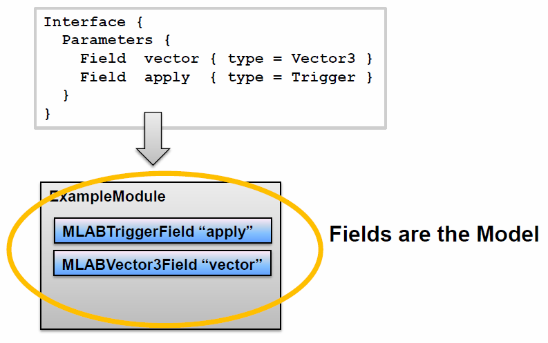
The fields defined in the interface sections are the models.
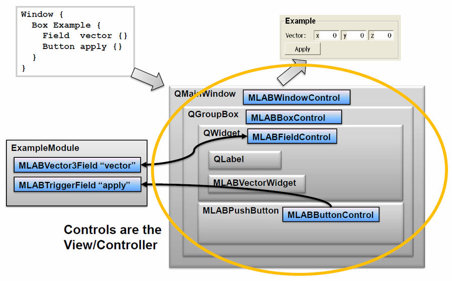
The controls in the GUI are the view and also the controller.
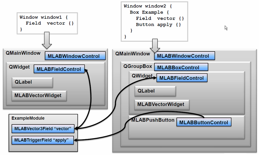
For a set of fields/models, many different views can be built.
It is important to keep this Model-view-control design in mind, otherwise it is easy to mix up the definition of fields (Interface section) with the GUI control of the field (Window section).
Model: defines a new field of type Vector3 named vector:
Interface {
   Parameters {
      Field vector { type = Vector3 }
      Field apply  { type = Trigger }
   }
}
View/Controller: defines a GUI control that shows the value of the existing vector field:
Window {
    Box Example {
      Field vector {}
      Button apply {}
    }
}![[Note]](images/note.png) | Note |
|---|---|
Admittedly, it's a bit misleading that the |
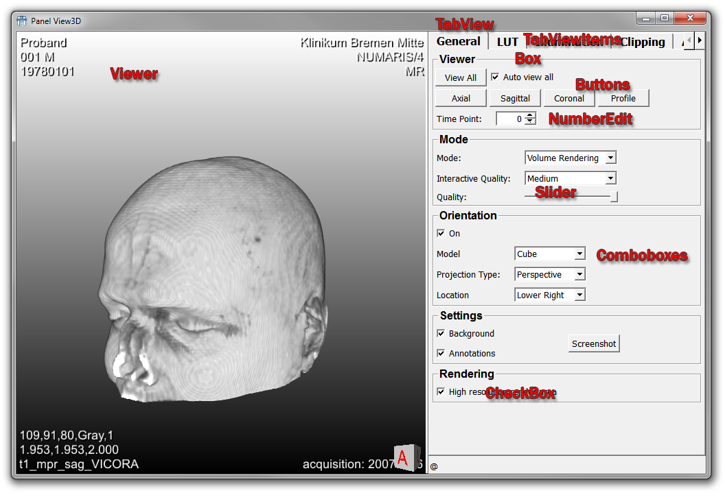
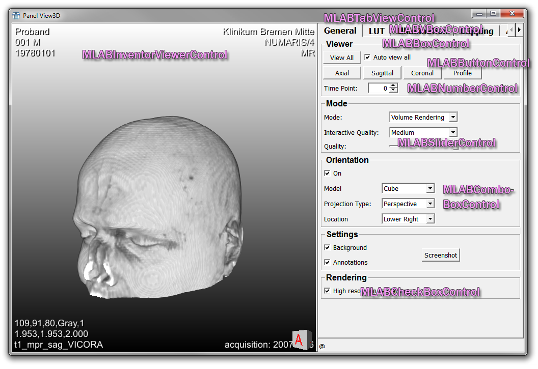
From the point of view of the MDL controls, the View3D panel looks like this:
The GUI definition of a module is written into the .script file of a module.
The Interface section is foremost used for Macro modules to declare fields. It is also used to declare extra fields of C++ modules or fields that should be kept persistent:
input fields
output fields
parameter fields
The fields defined here may also forward existing fields of sub modules (internal fields) instead of defining new ones.
Declaring parameter fields of a C++ module has the advantage that these fields can be made persistent to save their values along with the network. (Normally, internal module states are not saved when the network is saved.)
The Description section is optional and can be used for all module types. It contains definitions for:
Parameter field ranges (min/max)
Persistence
Editability
The Commands section is used to add Python script files and commands. (For details of the module initialization, see MDL Reference, chapter “Commands”.)
The Window section allows defining the GUI for the available Interface elements. The possible controls can be split into the following groups:
Input controls for viewing and editing field values (Field, CheckBox, etc.)
Layout controls (Vertical, Horizontal, Box, etc.)
Decoration controls (Label, Image, Separator, etc.)
See the MDL Reference for a complete list of available controls.
The number of Window sections — which is the number of panels for a module — is unlimited. See View3D as an example for multiple panels.
“Field” has two meanings in MeVisLab:
The Field in the Parameters section declares a field for a module.
Interface {
  Parameters {
    Field fieldName { type = String }
  }
}
The Field control in the Window section defines a GUI control.
Window {
  Category {
    Field fieldName {}
  }
}
In scripting these objects have different class names:
Fields from a Scripting Perspective
Fields can be accessed from scripting. Take this integer field as an example:
Interface {
   Parameters {
    Field intFieldName { type = Int }
  }
}
Getting and setting the value:
ctx.field("intFieldName").value = 13Getting and setting the value as a string (typically used for serialization purposes):
ctx.field("intFieldName").stringValue = "13"To force notification of all field listeners:
ctx.field("intFieldName").touch()FieldListener
The FieldListener binds scripting commands to a field. The command will always be called when the field issues a notification to its listeners.
| Note |
|---|---|
There is an important difference between FieldListeners defined in the Commands section and the ones defined in the Window section: The former is created when the module is created, and thus is always available. The latter is only created when the window is created, and it is destroyed when the window is destroyed. This will be explaind in the examples below. |
Example:
// triggerButton Field is already defined in Interface/Parameter
Interface {
Parameters {
Field triggerButton { type = Trigger }
}
}
Commands {
source = $(LOCAL)/ExampleToggleButton.py
FieldListener triggerButton { command = callGlobal }
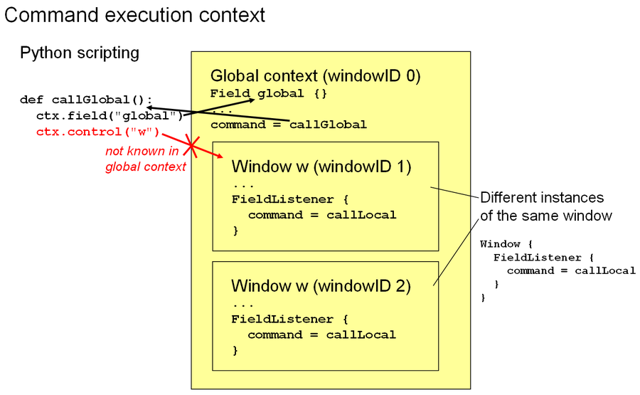
} Touching the trigger field in Python will cause a notification and the field listener will call the given command, which is “callGlobal” in this example:
ctx.field("triggerButton").touch()When “callGlobal” is called, there is no association to a window. The current window ID is 0, which means there is no current window. This means if you call ctx.control("controlName") in it, then MeVisLab will print an error that it cannot find the control.
If the field listener is defined inside of a window, it is only active when the window is actually created.
Window {
  Category {
    FieldListener triggerButton { command = callLocal }
  }
}
When “callLocal” is called, the current window ID is set to the window in which the field listener is defined. Calling ctx.control("controlName") in it will look inside this window for the control. This also means, that control names must only be unique inside a window, and can be reused in multiple windows of the same module.
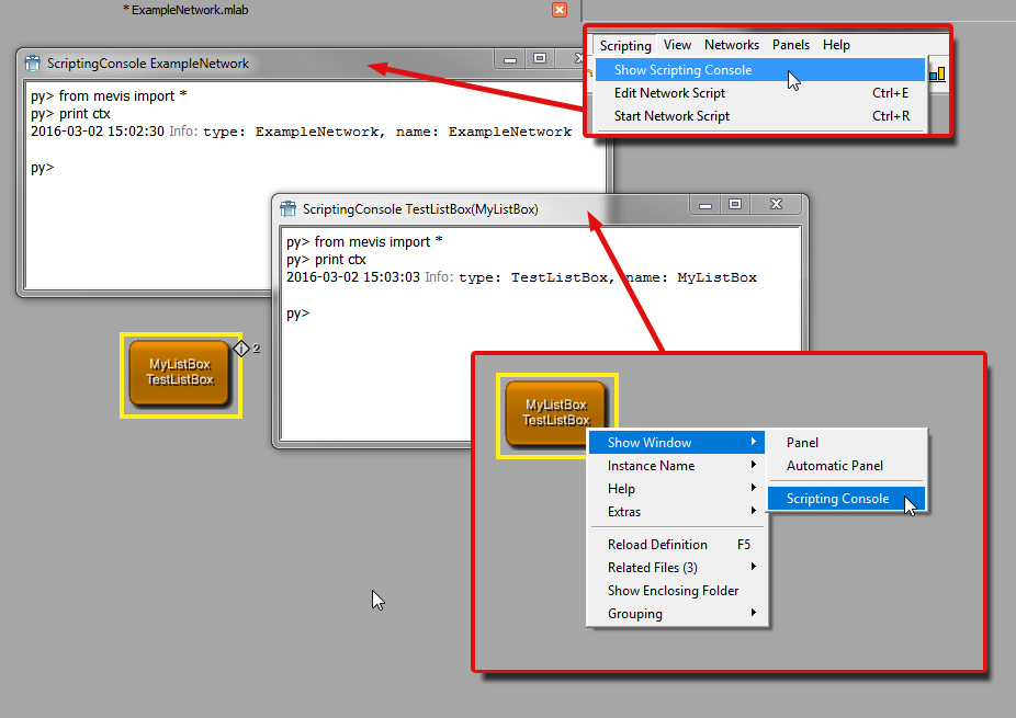
Accessing Controls from the Scripting Console
From the scripting console, looking up a control only works when the correct context is set. First, the module context must be right. The scripting console must be opened from the context menu of a module to have it as the current context. The scripting console that can be opened from the Scripting → Show Scripting Console menu has the current network and not the selected module as context. Second, the window ID is 0 by default. To look up a control the window ID must be set accordingly. For debugging purposes, the function ctx.controlDebug("controlName") can be used in the scripting console as an alternative to setting the current window ID. It looks for the control in all open windows.
The following figure demonstrates that the global scripting console is not associated to a selected module in the network. Although the panel of the TestListBox module is open, the control cannot be found. It can be found in the scripting console of the module itself.
© 2025 MeVis Medical Solutions AG
| | | |
| 10.4. Addition: Shifting the Whole Tip |  | 11.2. Developing the ExampleToggleButton |