DRR
- MLModule
genre
author
package
dll
definition
see also
keywords
Purpose
The module DRR creates a 2D DRR (Digitally Reconstructed Radiograph) projection of a 3D CT dataset with C-Arm device specific settings.
Usage
This module projects 2D radiographs from 3D datasets. In the current version, it is limited to the ray casting method that simulates an X-ray beam passing through the 3D image for each pixel of the output image. The beam path starts at a source and ends at a detector. Any voxels that are passed on the way from the source to the detector affect the resulting output image pixel. The type of effect can be selected by the Ray Casting Processing Mode parameter.
Generally, there are two different types of processing modes: built-in modes and LUT modes.
Built-in processing modes
Mean extinction projection: This projection is generated by adding up all voxels passed by the beam and dividing the sum by the number of voxels.
Maximum extinction projection: This projection uses the highest voxel value found in the beam path as value for the resulting pixel.
LUT based processing modes
This projection simulates a beam that starts with the intensity 1 and is attenuated by every voxel it passes. The attenuation coefficient of each voxel is defined in an external lookup table (LUT) that must be connected to the
inLUT. The attenuation coefficients must be in a range from 1 (no attenuation) to 0 (total extinction). After all target pixels have been calculated, they are scaled from the (0..1) range to the output image gray value range (0..2^b-1 with b as the output image bit depth).
By default, the center of the 3D voxel cube is aligned with the center of the source-detector line. This setup can be changed with the Input Image Settings parameters.
Windows
DRR
Input Fields
input0
- name: input0, type: Image
Input image. Needs to be a 3D CT image.
inLUT
- name: inLUT, type: DRRLUTFunction(MLBase)
LUT input. Needed by some (but not all!) algorithms.
Output Fields
output0
- name: output0, type: Image
Output image. Returns a 2D DRR.
Parameter Fields
Field Index
|
|
|
|
|
|
|
|
|
|
|
|
|
|
|
|
|
|
|
||
|
|
|
Visible Fields
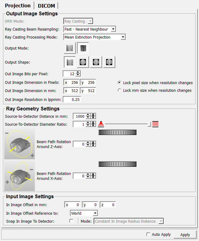
Ray Casting Beam Resampling
- name: beamResamplingMode, type: Enum, default: Fast - Nearest Neighbour
Defines how the input image voxels are collected that are part of a single beam.
Values:
Title |
Name |
|---|---|
Fast - Nearest Neighbour |
Fast - Nearest Neighbour |
Exact - Siddon |
Exact - Siddon |
DRR Mode
- name: DRRMode, type: Enum, default: Ray Casting
Defines the method of computing the DRR.
Values:
Title |
Name |
|---|---|
Ray Casting |
Ray Casting |
Ray Casting Processing Mode
- name: processingMode, type: Enum, default: Mean Extinction Projection
Defines how each passed voxel has an effect on the resulting projected value.
Values:
Title |
Name |
|---|---|
Mean Extinction Projection |
Mean Extinction Projection |
Maximum Extinction Projection |
Maximum Extinction Projection |
LUT Based Projection |
LUT Based Projection |
Output Shape
- name: outputShape, type: Integer, default: 0
Defines the shape of the output image.
Presets are rectangular, circular, and hexagonal.
Output Mode
- name: outputMode, type: Integer, default: 0
Defines the output mode.
Presets are negative (like usual film radiographs) or positive (like on X-ray display devices or fluoroscopes).
Out Image Bits per Pixel
- name: outImageBitsPerPixel, type: Integer, default: 12, minimum: 1, maximum: 16
Sets the gray value depth in bits per pixel.
Out Image Dimension in Pixels
- name: outImageDimension_inPixels, type: Vector2, default: 256 256
Sets the output image’s extent in pixels.
Out Image Dimension in mm
- name: outImageDimension_in_mm, type: Vector2, default: 512 512
Sets the output image’s extent in millimeters.
Resolution Lock Mode
- name: resolutionLockMode, type: Enum, default: Lock pixel size when resolution changes
Defines which unit shall be left unchanged if the resolution changes.
Values:
Title |
Name |
|---|---|
pixel size when resolution changes |
Lock pixel size when resolution changes |
mm size when resolution changes |
Lock mm size when resolution changes |
Out Image Resolution in lppmm
- name: outImageResolution_in_lppmm, type: Float, default: 0.25
Sets the output image’s extent in lppmm (line pairs per mm, 1 lppmm = 2 pixel per mm).
Source-to-Detector Distance in mm
- name: distanceSourceToDetector_in_mm, type: Integer, default: 1000
Sets the distance of the beam source to the detector.
Source-To-Detector Diameter Ratio
- name: sourceToDetectorDiameterRatio, type: Float, default: 1, minimum: 0, maximum: 1
Sets the ratio of the beam source area to the beam detector area.
If it is set to 1, the source area is the same size as the detector area, resulting in a parallel beam projection. If it is set to 0, the source area is point-shaped therefore resulting in an (ideal) cone beam projection.
Any ratio in between is possible, allowing for the simulation of non-ideal (non-point-shaped) ray sources.
Beam Path Rotation<br>Around Z-Axis
- name: beamPathRotationAroundZAxis, type: Integer, default: 0, minimum: -360, maximum: 360
Sets the rotation of the beam path around the z-axis of the 3D input image in degrees (full 360° rotation).
A positive angle indicates a clockwise rotation, a negative angle a counterclockwise rotation.
Beam Path Rotation<br> Around X-Axis
- name: beamPathRotationAroundXAxis, type: Integer, default: 0, minimum: -360, maximum: 360
Sets the rotation of the beam path around the x-axis of the 3D input image in degrees (full 360° rotation).
In Image Offset in mm
- name: inImageOffsetIn_mm, type: Vector3, default: 0 0 0
Sets the dislocation in millimeters of the rotation center, which is in the input image’s center by default.
Affects
In Image Offset Reference to.
In Image Offset Reference to
- name: inImageOffsetMode, type: Enum, default: World
Defines how the
In Image Offset in mmis interpreted.
Values:
Title |
Name |
Description |
|---|---|---|
World |
World |
The offset takes effect in the direction of the input image’s main axes. 
|
Beam Path |
Beam Path |
The offset takes effect relative to the beam path. 
Hint: this option dislocates the output image independently from the beam path settings. A 100 mm offset in x-direction in this mode mode always pushes the output image 100 mm to the right, regardless what beam path rotation is selected. A 100 mm offset in World mode causes different positions of the output image depending on the beam path, because the input image might move out of the beam path. |
Snap In Image To Detector
- name: inImageSnapToDetector, type: Bool, default: FALSE
If checked, the
In Image Offset Reference tois set to Beam and values are being calculated automatically.The x and y offsets are set to zero (centering the image along the beam path), and the z offset is calculated to position the input image as close as possible to the detector without overlapping it.
Checking this option makes the
Modeavailable.
Mode
- name: inImageSnapToDetectorMode, type: Enum, default: Constant In Image Radius Distance
Defines the mode for automatic parameter calculation.
Values:
Title |
Name |
Description |
|---|---|---|
Constant In Image Radius Distance |
Constant In Image Radius Distance |
The distance to the detector is calculated based on the radius (i.e., the maximum distance from the center to the edge) of the input image. This ensures a constant distance from the input image center to the detector, regardless of the projection angle. This mode is ideal to get a series of comparable images, because there is no angle-related perspective distortion. 
|
Minimum Distance |
Minimum Distance |
The distance from the input image to the detector plane is calculated to the smallest possible value. It depends on the angle of the projection. 
|
Auto Apply
- name: autoApply, type: Bool, default: FALSE
If checked, all changes to any field computes the output image anew.
Apply
- name: apply, type: Trigger
When pressed, the output image is computed anew.
Image Laterality
- name: imageLaterality, type: String, default: U
Defines the laterality of the image using a DICOM tag.
Positioner Type
- name: positionerType, type: String, default: NONE
Defines the positioner type using a DICOM tag.