PCLToInventor
- MLModule
genre
author
package
dll
definition
see also
inherits from
keywords
Purpose
PCLToInventor converts a point cloud from the Point Cloud Library (PCL) to an Open Inventor SoVertexProperty which is provided at the first output. Some more convenience outputs, a SoPointSet, a SoLineSet, and a SoIndexedFaceSet are also provided to easy the display of the point cloud or surfaces without the need to instantiate too many other modules.
Important:
When using point sets with transparency (for example when setting Where To Store Value to ScaleToOrderedRGBA ) it is highly recommended to explicitly define the OpenGL blend mode in the OpenInventor Scene graph, otherwise the transparency settings may result in undefined visualizations. Best use a SoBlendMode with enabled SoBlendMode.enabled = TRUE before drawing anything using PCLToInventor.
Important: When rendering points of a cloud then usually the problem appears how the intensity or transparency of the drawn points shall be defined, especially if the points do not have a member defining an intensity. Therefore a value called “Intensity Replacement” can be used which uses another member if no appropriate one is available. For the listed point types the following member values are used as intensity:
pcl::PointXYZ: Always 0
pcl::PointXYZLNormal: curvature
pcl::PointXYZRGBNormal: curvature
pcl::PointXYZINormal: intensity
Note that the RGB components of the pcl::PointXYZRGBNormal are usually not used as intensity replacement, because it contains more than an intensity and also an alpha value. When rgba shall be used then set Where To Store Value to UseOnlyRGBA.
Windows
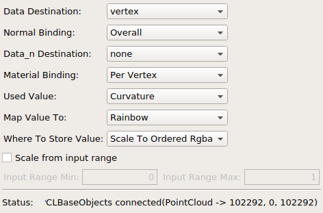
Default Panel
Input Fields
inputPCLObject0
- name: inputPCLObject0, type: MLBase
Here the point cloud must be connected which shall be converted mainly to
SoVertexProperty.
Output Fields
outputSoVertexProperty
- name: outputSoVertexProperty, type: SoNode
At this output the
SoVertexPropertyis provided for use in other modules. On failed conversions, open inputs or empty connected point clouds the entries of theSoVertexPropertyare set to zero elements.
outputSoPointSet
- name: outputSoPointSet, type: SoNode
This is a convenience output of a SoPointSet module in the default state that it shows all points from the inventor state.It can be connected in the inventor scene directly after the first output to draw all coordinates as a point set.
outputSoIndexedFaceSet
- name: outputSoIndexedFaceSet, type: SoNode
At this output the
SoIndexedFaceSetis provided for use in other modules. It will be set with useful indexes only if the input connector contains a pcl::PolygonMesh with vertex indexes. These indexes will be set such that they reference points set inoutputSoVertexProperty.
outputSoLineSet
- name: outputSoLineSet, type: SoNode
This is a convenience output of a SoLineSet module. Its numVertices member is filled with as many 2’s as there are pairs from (data, data+data_n) coordinates in the SoVertexProperty.vertex member. This requires that both, the field
Data DestinationandData_n Destinationare set to vertex.
Parameter Fields
Field Index
|
|
|
|
|
|
|
|
|
|
|
|
|
|
|
Visible Fields
Status
- name: status, type: String, persistent: no
Displays information about the connection status. If valid data is assigned to the vertex property after the status in parentheses the number of assigned data entries, the number of assigned data_n, and the number of intensity replacement values is listed.
see also PCLModule.status
Data Destination
- name: data012Destination, type: Enum, default: vertex
Data Destinationcontrols where the values of the points[].data members are stored. Using other modes than “vertex” is rarely useful.
Values:
Title |
Name |
Description |
|---|---|---|
none |
none |
The three member values are not stored at all in the |
vertex |
vertex |
The three member values are stored in the .vertex coordinates of the |
normal |
normal |
The three member values are stored in the .normal coordinates of the |
texture Normal |
textureNormal |
The first two member values are stored in the .textureNormal coordinates of the |
ordered RGBA |
orderedRGBA |
The four member values are stored in the .orderedRGBA values of the |
Normal Binding
- name: normalBinding, type: Enum, default: OVERALL
For details see the documentation of the same named field in
SoVertexProperty.
Data_n Destination
- name: data_n012Destination, type: Enum, default: none
Data_n Destinationcontrols where the values of the points[].data_n members are stored if they exist. If these values are not part of the connected point cloud then NULL vectors are written instead. The modes behave in the same way as they do forData Destination, however, they are performed after them. Note that if both,Data DestinationandData_n Destinationare set to vertex, then pairs of coordinates of type (point.data[x], point.data[x]+point.data_n[x]) will be added to the SoVertexProperty.vertex member, i.e. the twice as many vertices will be created. This is especially useful when theoutputSoLineSetshall be used. See example network ofPCLNormalEstimationfor a display example of normals.
Material Binding
- name: materialBinding, type: Enum, default: PER_VERTEX_INDEXED
For details see the documentation of the same named field in
SoVertexProperty.
Where To Store Value
- name: whereToStoreValue, type: Enum, default: SCALE_TO_ORDERED_RGB, deprecated name: whereToStoreIntensityReplacement
Describes where the value of the points (see
Used Value) shall be stored in the internally used SoVertexProperty.rgba field. The intensity replacement is that point member which normally can be used best in visualizations as intensity, even if the point does not have a value explicitly defined as such a value. See Purpose for the list of members used as this.
Values:
Title |
Name |
Description |
|---|---|---|
To Nowhere |
TO_NOWHERE |
The value (whichever is used, see |
Scale To Ordered Rgb |
SCALE_TO_ORDERED_RGB |
The value selected with
|
Scale To Ordered Rgba |
SCALE_TO_ORDERED_RGBA |
The value selected with
|
Use Only Rgba |
USE_ONLY_RGBA |
This mode makes rgba members directly used as the SoVertexProperty.rgba values. If the input cloud does not have an rgba member, then the value 0x00000000 is used which draws the points black and transparent. |
Used Value
- name: usedValue, type: Enum, default: USE_INTENSITY_REPLACEMENT
If a point shall be displayed usually a value is needed which to describe the displayed intensity or color. Since not all PCL points have the same fields, here either the intensity replacement or the curvature can be selected.
Values:
Title |
Name |
Description |
|---|---|---|
Intensity Replacement |
USE_INTENSITY_REPLACEMENT |
The member from the point which best can be used as intensity. |
Curvature |
USE_CURVATURE |
The curvature member value from the point if the point has one; otherwise 0 is used instead. |
Map Value To
- name: mapValueTo, type: Enum, default: MAP_VALUE_TO_GREY
Usually a value is clamped to the range [0,1] and then mapped to an intensity or color.
Values:
Title |
Name |
Description |
|---|---|---|
Grey |
MAP_VALUE_TO_GREY |
The value from the point is clamped to [0,1] and then mapped to RGB values representing a color map from black to white. |
Rainbow |
MAP_VALUE_TO_RAINBOW |
The value from the point is clamped to [0,1] and then mapped to RGB values representing a rainbow map from [Red…Green…Blue…Violet]. |
Scale From Input Range
- name: scaleFromInputRange, type: Bool, default: FALSE
If false then incoming float values (such as intensity replacement or curvature) are assumed to be from [0,1] for color mapping; if true then [
Input Range Min,Input Range Max] is used for mapping the input values to the color range. Values outside will be clamped to the interval limits. RGB, RGBA, or vector data sources and destinations such none, vertex, normal and texture normal are not affected.
Input Range Min
- name: inputRangeMin, type: Float, default: 0
Minimum of interval in which floating point input values (such as intensity replacement or curvature) are assumed to map them to color range, must be smaller than
Input Range Max. Insensitive and not used ifScale From Input Rangeis off.
Input Range Max
- name: inputRangeMax, type: Float, default: 1
Maximum of interval in which floating point input values (such as intensity replacement or curvature) are assumed to map them to color range, must be larger than
Input Range Min. Insensitive and not used ifScale From Input Rangeis off.