Open Inventor
Introduction
In order to simplify your graphics programming effort dramatically and to decrease your programming time, Open Inventor includes a rich set of various objects such as cubes, polygons, text, materials, cameras, lights, trackballs, handle boxes, 3D viewers etc.
To make your representation as real as possible you can define material properties (colors, textures, transparencies), shapes, transformations, animations by engines. You can also add lights and cameras to your scene.
What can users do with objects?
- define and manipulate their shapes, sizes, materials, textures …
- apply spatial manipulations
- add and remove objects or parts of objects
- represent, save, load and print them
- use them for further processing
- animate them by engines
Open Inventor presents a programming model based on a 3D scene database which consists of various nodes. Each node holds a piece of information and is composed of a set of data elements, called fields, that describes the parameters of the node. The collection of nodes for representation is called scene graph. Note that you should define properties before shapes, because otherwise you will not see any effect of this properties.
Open Inventor in MeVisLab
In MeVisLab most of the Inventor nodes are represented by modules, and the modules are organized like the nodes in Inventor, i.e. we have a cube operator for the cube node, a material module for the material node etc. See ‘Modules’ to get an idea of our module concept.
This concept provides fast and easy programming, the user is not required to know C++ programming, OpenGL and so on. The only thing to be done is to input the parameters of the module, that means to parametrize the fields of the node (but there are default values, too). You can find more about this in the next chapter: ‘Scene Graph’.
Using Open Inventor in MeVisLab does not require C++ coding, so this concept avoids typing mistakes and compiling errors, you can quickly see a result on the screen and easy change the parameters of the object(s) without new compiling.
The only thing you have to do is to make up a scene graph in mind or on paper, then select the required operators, connect them, define their parameters and look at the result.
The Scene Graph
What is a Scene Graph?
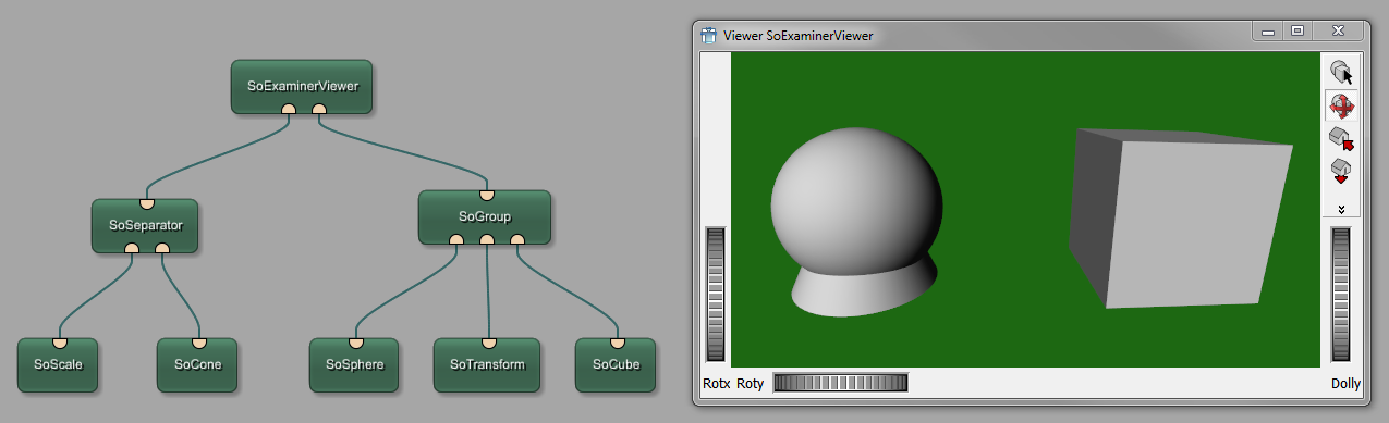
Inventor scenes are organized in structures are called scene graphs. A scene graph is made up of nodes, which represent 3D objects to be drawn, properties of the 3D objects, nodes that combine other nodes and are used for hierarchical grouping, and others (cameras, lights, etc). This nodes are called shape nodes, accordingly, property nodes, group nodes and so on. Each node contains one or more pieces of information stored in fields. For example, the SoSphere node contains only its radius, stored in its radius field.
The purpose of an Open Inventor file or program is to describe what is referred to as a scene graph. You can think of a scene graph as a diagram that has a bunch of lines connecting a bunch of points. The points are the objects and properties (called nodes in Open Inventor) that interest you, like a cube, or a cone, or the ability to rotate something around the x-axis by 45 degrees. The lines are an indication of the relationship between the points.
For example, collections of simple objects can be grouped together to form a more complex object, in which case the node for the complex object would be referred to as the parent node and the simple objects would be referred to as child nodes. Once you have a scene graph, you can use a type of program that is referred to as a viewer to render the scene so that you can see what it looks like. (On top you have always one kind of output node, i.e. viewer, write action, print dialog.) The picture shows how our Inventor scene graph looks like. We see a directional light node to modify the lighting property, a sphere node for defining a shape and an examiner viewer node to render the constructed scene.
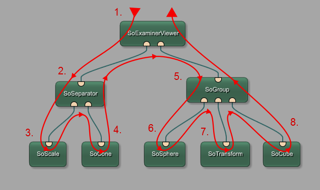
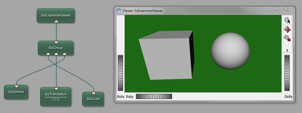
During rendering the scene graph is traversed, starting from the root node, from left to right, from top to bottom. Nodes to the right (and down) in the graph inherit the traversal state set by nodes to the left (and above), That is why order is important for defining properties to shapes.
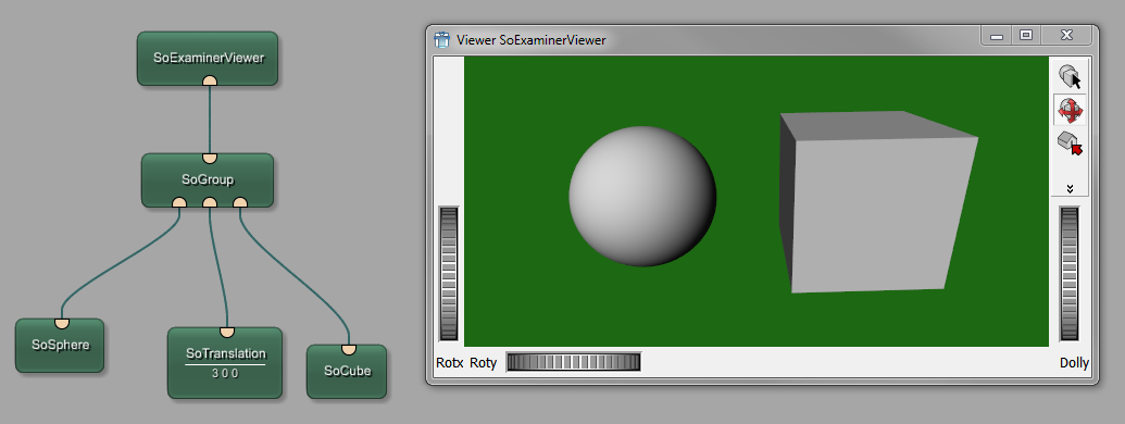
Changing the order of evaluation changes the resulting scene.
Nodes and Fields
Open Inventor has many different kinds of nodes that you can put into a scene graph. One kind of node is used to describe cones, another kind of node is used to describe the surface appearance of objects, etc. Each of these kinds of nodes is referred to as a class. All the nodes in a particular class have the same kinds of properties, like height, or width, or location. During traversing the scene graph each node depending from its fields modifies the traversal state, which is a collection of elements or parameters.
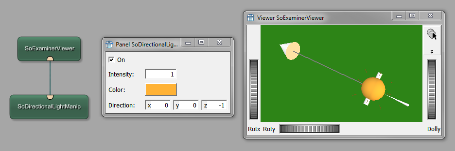
This picture shows a panel with the fields of the directional light node used above. You can modify using direction, color components and intensity of the light. During rendering this properties are applied to the sphere.
The nodes are instances of various Open Inventor classes. If you can have more than one instance of any particular class of node, each with different characteristics, how does Open Inventor know if, for example, you want one cone to be tall and another cone to be short? It keeps track of this information with fields. In the case of the two cones you would set the height field differently for each cone. Different classes of nodes have different collections of fields for you to use. Learning how to use a node class involves learning what the fields are, what values they can have, and what effect different field values will have on your scene when you view it.
Field Connections
It is possible to connect two or more fields so that they share the same value. If the field value for the source (there can only be one source) of the connection changes, Open Inventor automatically updates the value for the field on the destination end of the connection. One important use of field connections is in animation. Since the values of the fields in the nodes help to determine what a scene looks like, if you use connections that will make field values change over time, your scene will change appearance over time, which is done by so called engines.