SoCoordinateSystem
Purpose
The module SoCoordinateSystem displays labeled coordinate axes for an ML image or an Inventor scene.
The module creates axes describing the axis-aligned bounding box of either input.
Input Fields
The module SoCoordinateSystem uses the first valid connection from left to right as input to determine the axes’ sizes and positions.
Parameter Fields
Field Index
Arrow Length Factor: Float |
lettersFontAlpha: Float |
Use Voxel Aligned Bounding Box: Bool |
Axis Color: Color |
Numbers Font Color: Color |
User Scale: Vector3 |
axisAlpha: Float |
numbersFontAlpha: Float |
User Stride: Double |
End Tick Mode: Enum |
Stride Mode: Enum |
User Transform Mode: Enum |
Font Size: Float |
Text Shadow Color: Color |
User Translate: Vector3 |
Letter Offset Factor: Float |
Tick Color: Color |
|
Letters Font Color: Color |
tickAlpha: Float |
|
Letters Font Size Offset: Float |
Use Text Shadow: Bool |
Visible Fields
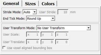
Stride Mode
-
name:strideMode, type:Enum, default:AUTO¶ Defines how the distance between ticks is determined.
Values:
| Title | Name | Description |
|---|---|---|
| Auto | AUTO | Strides are computed automatically by finding the (rounded) magnitude of the maximum axis length and dividing that magnitude value by 10. For example, a maximum axis length of 23 mm would lead to a rounded magnitude of 10, resulting in a stride of 1 mm. A maximum axis length of 56 mm would lead to a rounded magnitude of 100, resulting in a stride of 10 mm. |
| User | USER | The value of the field User Stride is used. If using this value would lead to either too many ticks (stride too low) or no tick at all (stride to high), the automatic stride is used and message is printed to the console. |
End Tick Mode
-
name:endTickMode, type:Enum, default:ROUND_UP¶ Defines the mode for the end tick.
Values:
| Title | Name | Description |
|---|---|---|
| Precise | PRECISE | Generates a tick at the precise position of an axis’ absolute length (if it isn’t in 1% tick distance of another tick). |
| Round Up | ROUND_UP | Round number of ticks up to accommodate the current axis’ length. |
| Round Down | ROUND_DOWN | Round number of ticks down to accommodate the current axis’ length. |
| Round Nearest | ROUND_NEAREST | Round number of ticks to nearest value to accommodate the current axis’ length. |
Axis Color
-
name:axisColor, type:Color, default:1 1 1¶ Sets the color of the axis lines and the end arrows.
Numbers Font Color
-
name:numbersFontColor, type:Color, default:1 1 1¶ Sets the color of the numbers.
Letters Font Color
-
name:lettersFontColor, type:Color, default:1 1 1¶ Sets the color of the axis letters (X, Y, Z).
Use Text Shadow
-
name:useTextShadow, type:Bool, default:TRUE¶ If checked, the letters and numbers are rendered using a text shadow.
Text Shadow Color
-
name:textShadowColor, type:Color, default:0 0 0¶ Sets the color of the text shadow.
Font Size
-
name:fontSize, type:Float, default:10, minimum:4, maximum:30¶ Sets the font size in pixel on screen.
Letters Font Size Offset
-
name:lettersFontSizeOffset, type:Float, default:2¶ Sets a offset in mm to enlarge the letters (X, Y, Z).
Arrow Length Factor
-
name:arrowLengthFactor, type:Float, default:2¶ Sets a factor to control the end arrows’ length.
Letter Offset Factor
-
name:letterOffsetFactor, type:Float, default:2¶ Sets a factor to control the position of an axis letter in the direction of the axis.
Use Voxel Aligned Bounding Box
-
name:useVoxelAlignedBoundingBox, type:Bool, default:FALSE¶ If checked, the coordinate system is generated as a local coordinate system of the input voxel image.
User Scale
-
name:userScale, type:Vector3, default:1 1 1¶ Sets a component-wise scale to the axes.
User Translate
-
name:userTranslate, type:Vector3, default:0 0 0¶ Sets a translation for the whole coordinate system.
User Transform Mode
-
name:userTransformMode, type:Enum, default:NO_USER_TRANSFORM¶ Defines how the user transformations (
User Scale,User Translate) are applied.
Values:
| Title | Name | Description |
|---|---|---|
| No User Transform | NO_USER_TRANSFORM | The user-defined transformation is not applied at all. |
| User Transform Instead Of Input | USER_TRANSFORM_INSTEAD_OF_INPUT | The user-defined transformation is used instead of any input information. Attached ML images and Inventor scenes are disregarded. |
| Apply User Transform To Input | APPLY_USER_TRANSFORM_TO_INPUT | The user-defined transformation is applied to the input information if available. Otherwise, the user-defined transformation is applied to the default coordinate system. |