MergeRegions
-
MLModule¶ genre Subimageauthor MeVis Medical Solutions AGpackage MeVisLab/Standarddll MLGeometry1definition MLGeometry1.def see also ModifyRegion,SubImagekeywords bounding,box,roi,mask,world,coordinates,match
Purpose
The module MergeRegions offers operations to combine a number of regions described by multiple input images that usually represent different regions of a single volume.
The input images representing the regions must have identical orientation, voxel size and voxel grid translation (see details section for exceptions) and are registered via their translation in the world coordinate system.
The number of images to be combined is user-defined and can be set between 2 and 20.
Usage
Select the number of images you would like to combine and the region the output image(s) shall describe. If you want to combine the image data itself, you can also select a merge mode (for example a maximum operation).
Details
- Use the
Merge Modefeature with care, behavior is not always consistent, especially if 0 is passed for any of the C values or non-0 values forFill Value. Note that, if one of the merging modes does not appear to work properly for your data, you can always select mode None and compose the output images with other modules such as Mask or Arithmetic (FME release package)- In particular, if the output data type minimum (maximum) value is the result of a maximum (minimum) operation at some positions, the results of an operation using min or max might be incorrect at these positions. This is due to the ‘in-place’ approach and having to initialize the output memory with something within the data type range.
- The module’s main purpose is to cut out and associate images that live in the same world coordinate system and use the same voxel grid. Thus, it is assumed that all input images have identical orientation, voxel size, and are aligned in terms of translations, meaning that their voxel grids must be identical. In other words, only origin and extent of the input images may differ. We refer to this by saying that the images are based on identical voxel grids. This restriction ensures that voxel-base image combinations based on the module’s outputs (
Merge Mode== None) or within the module (Merge Mode!= None) always associate corresponding voxels. If the voxel grids are not identical, there are two possibilities:
- The input image voxel grid differences are reasonably small (see
Voxel Grid Alignment Tolerance). In this case, the module simply pretends the grids are identical and continues to work as before, except that it deals with the slight coordinate differences in the following way:
- If
Merge Mode== None, the grid of the corresponding input N is used for each output N.
- In any other
Merge Mode(where there is only one output, output0):
- If the
Use Regionmode is set to “use input N”, the grid of input N is used for the only output (0).- If the
Use Regionmode is NOT set to “use input N”, the grid of the first valid input image is used for the only output (0).
- The input image voxel grid differences are too big (with respect to
Voxel Grid Alignment Tolerance) to be ignored.
- If
Merge Mode!= None orEnable support for input images with unaligned voxel grids== False, the output is invalid and an error message is given in thestatusfield.- Only for
Merge Mode== None, this behavior can be overridden by settingEnable support for input images with unaligned voxel gridsto True. Although it is then no longer assured that all output images have the same orientation, voxel size, translation and extent and can thus no longer be combined on a voxel-only base, this can sometimes make sense as long as images have the same (or orthogonal) orientation. Have a look at theEnable support for input images with unaligned voxel gridsdocumentation for details on how this works.
MeVis only: There is a macro module called MergeRegionsExt extending this module’s functionality by combining it with a ModifyRegion macro module (to allow additional ROI modifications) as well as resampling operators (to align the voxel coordinates of images with different voxel sizes).
Interaction
- Each input image or parameter change is directly relayed to the output image(s).
- For all merge modes with special treatment of input0 except Bitwise Write with LUT, the first input (input0) must be connected to a valid image in order to obtain an output image.
Tips
Note: An exact region can only be computed for the x/y/z dimensions. Since the c/t/u dimensions do not possess a global reference coordinate system as the x/y/z do, only the c/t/u-extent of the given image (or, for a custom world box, the c/t/u start and end indices) is (are) taken into account. Any c/t/u dimension info is neglected, and for the output image c/t/u dimension info, only clamping to the new size is performed.
Input Fields
The module has as many inputs as specified by Maximum Number of Active Image Connections.
Depending on the selected merge mode, different configurations of unconnected inputs are allowed.
Output Fields
The number of outputs depends on the Merge Mode:
Merge Mode== copy only: The number of outputs equals the number of inputs. Every output whose input is connected will display its input image in the selected region (if valid).Merge Mode!= copy only: The module has only one (active) output. Output0 will display the result of the selected merge operation with respect to the selected region (if valid). All other outputs will be invalidated (and hidden, if possible).
Parameter Fields
Field Index
#: Integer |
Merge Mode: Enum |
-> Outbox (in WC): String |
Output Valid: Bool |
Allow invalid inputs: Bool |
status: String |
Auto update: Bool |
Update: Trigger |
Clear: Trigger |
Use Region: Enum |
Enable support for input images with unaligned voxel grids: Bool |
Voxel Grid Alignment Tolerance: Double |
Fill Value: Double |
|
Maximum Number of Active Image Connections: Integer |
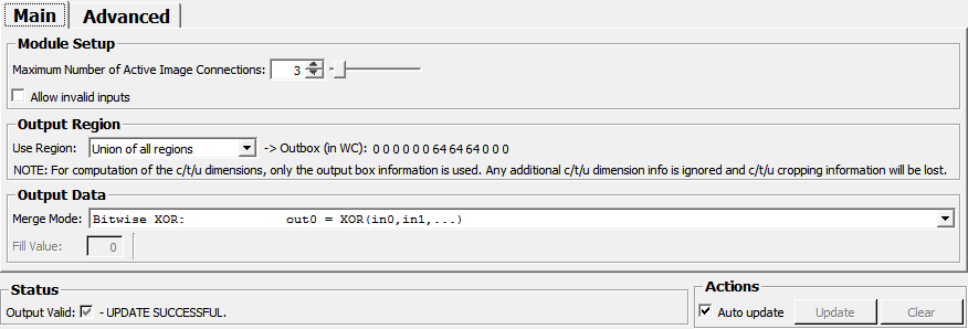
Visible Fields
-> Outbox (in WC)
-
name:outWorldBox, type:String, default:0 0 0 0 0 0 -1 -1 -1 -1 -1 -1¶ Shows the current output box using world coordinates. In the region modes representing input image regions (so everything except custom mode where the box is manually specified by the user) the world box will be computed to point to corner voxel corners to represent the entire region that is covered by the voxels. NOTE: When converting back to voxel coordinates, it is not immediately clear that one will get the correct voxel coordinates again since slight rounding errors might cause the image region to enlarge. However, MergeRegions normally prevents that by applying a small epsilon (see
Voxel Grid Alignment Tolerance) when converting the world box to a voxel box again for each input image.In custom region mode, an external modification to this field results in an actual change on the output(s).
Fill Value
-
name:fillValue, type:Double, default:0¶ Sets the fill value (fV) for undefined image regions.
Use Region
-
name:selectROI, type:Enum, default:UseInputRegion¶ Defines the region of interest to work on.
Note: An exact region can only be computed for the x/y/z dimensions. Since the c/t/u dimensions do not possess a global reference coordinate system as the x/y/z do, only the c/t/u-extent of the given image (or, for a custom world box, the c/t/u start and end indices) is (are) taken into account. Any c/t/u dimension info is neglected, and for the output image c/t/u dimension info, only clamping to the new size is performed.
Values:
| Title | Name | Deprecated Name | Description |
|---|---|---|---|
| Region from input0 (deprecated, use UseInputRegion instead) | UseRegion0_deprecated | Use region from input0,UseRegion0 | |
| Region from input1 (deprecated, use UseInputRegion instead) | UseRegion1_deprecated | Use region from input1,UseRegion1 | |
| Region from input2 (deprecated, use UseInputRegion instead) | UseRegion2_deprecated | UseRegion2,Use region from input2 | |
| Region from input3 (deprecated, use UseInputRegion instead) | UseRegion3_deprecated | UseRegion3,Use region from input3 | |
| Input Region | UseInputRegion | The exact region of one of the inputs is used for the output image(s). The index of the input is described in the number field (#) appearing on the right hand side of the region selection field. Possible values for the number range from 0 to (Maximum Number of Active Image Connections - 1). |
|
| Union of all regions | UseUnion | Use union of all regions | The union of the regions of all input images is used. |
| Intersection of all regions | UseSection | Use section of all regions | The intersection of the regions of all input images is used. |
| Custom region | UseCustomRegion | Use custom region | The region specified by the field Output image box will be used. It is a SubImgBoxf-field that can be modified manually, by using |
#
-
name:roiSourceIndex, type:Integer, default:1, minimum:0, maximum:1¶ Shows the number of used input regions.
Maximum Number of Active Image Connections
-
name:numActiveImages, type:Integer, default:2, minimum:2, maximum:20¶ Sets the number of image connections that are displayed in the network and used for output computation.
Note that it is not possible to decrease this value further if this would cause one of the current connections to become inactive. The maximum value of active is fixed (currently at 20) and can only be changed in the source code.
Allow invalid inputs
-
name:allowInvalidInputs, type:Bool, default:FALSE¶ If set to false, no update is possible if any of the active inputs is invalid, independent of
Use RegionandMerge Mode.
Enable support for input images with unaligned voxel grids
-
name:allowDifferentInputImageGridsInCopyMode, type:Bool, default:FALSE¶ This flag can be used to enable region merging (
Merge Mode== None) support for input images with different orientations, resolutions or voxel grid translations. Note that this only really makes sense if at least the input image orientations are identical (or orthogonal) since otherwise the-> Outbox (in WC)that is used to cut out input image regions will not make sense for all images. If the flag is enabled, the world box is applied to each input image individually like theSubImagemodule does it in ‘world box’ mode. Of course, it is then of course no longer assured that all output images have the same orientation, voxel size, translation and extent, and they can thus no longer be safely combined on a voxel-by-voxel base.
Voxel Grid Alignment Tolerance
-
name:worldToVoxelGridConversionTolerance, type:Double, default:0.001, minimum:0, maximum:0.49¶ The
Voxel Grid Alignment Toleranceis a tolerance parameter that is always to be interpreted as a floating point voxel coordinate (FPVC) offset (i.e. a value of 1e-4 with a voxel size of (0.1,1,2) would result in dimension-specific tolerances of (1e-5, 1e-4, 2e-4)). It has two uses:- Epsilon used to translate the world box into a voxel box for each particular image: If a world coordinate is closer than
Voxel Grid Alignment Tolerance(as FPVC) to any voxel border, it is assumed to be located exactly on the border. This prevents minuscule ‘overhangs’ caused by rounding errors to result in the undesired enlargement of the output image, or in apparent misalignment. The epsilon is always applied for the conversion, including the case whenEnable support for input images with unaligned voxel gridsis enabled. The only difference in this case is that even if the grids differ by more than the given tolerance, the module still computes an output (but only in ‘None’ merge mode). - If
Enable support for input images with unaligned voxel gridsis disabled, the value is also used to find out if the input images are sufficiently aligned within the output region. This means that any corner position of the output region must not be farther away from a voxel corner in any of the input images thanVoxel Grid Alignment Tolerance(as FPVC). Of course, in addition, the number of voxels in each dimension must be the same for all input images for the alignment test to pass.
A typical value for
Voxel Grid Alignment Toleranceis 1e-4 (1/10000 of a voxel).- Epsilon used to translate the world box into a voxel box for each particular image: If a world coordinate is closer than
Merge Mode
-
name:mergeImgMode, type:Enum, default:None¶ Defines the merge mode.
Values:
| Title | Name | Deprecated Name | Description |
|---|---|---|---|
| Copy only: outX = inX; X = 0,1,… | None | [ 0] none | Every output whose corresponding input is connected to an image will put out exactly the input image, but with respect to the selected region. In every other mode, only the first output image (output0) will be used. |
| Maximum: out0 = MAX(in0,in1,…) | Maximum | Max | output0 holds the maximum of the available input images.
Where no input image is defined, the Note that the special case where the output datatype is of unsigned integer (i.e. has a minimum of 0), the specified |
| Minimum: out0 = MIN(in0,in1,…) | Minimum | output0 holds the minimum of the available input images. Where at least one input image is undefined, the Fill Value is written. Try MinWhereDefined mode if this is not what you are looking for. |
|
| Minimum where defined: out0 = MIN(inX; X = 0,1,… and inX defined) | MinWhereDefined | Min | At each position, output0 holds the minimum of the input images where this position is defined (i.e. within the image region). Only if the position is defined by none of the input images, the Note that problems might arise if the maximum value for the output data type is used within one of the input images, where all other input images are not defined (because the that output data type maximum is used for initialization of the minimum-operation). |
| Bitwise OR: out0 = OR (in0,in1,…) | BitWiseOr | [ 3] out0 = OR (i0, i1, i2, i3) (bitwise OR) | output0 holds the bit-wise OR of the available input images. Note that the In floating point images, Maximum mode will be used instead. |
| Bitwise AND: out0 = AND(in0,in1,…) | BitWiseAnd | [ 4] out0 = AND (i0, i1, i2, i3) (bitwise AND) | output0 holds the bit-wise AND of the available input images where all images are defined (otherwise the In floating point images, Minimum mode will be used instead. |
| Bitwise XOR: out0 = XOR(in0,in1,…) | BitWiseXor | [12] out0 = XOR (i0, i1, i2, i3) (bitwise XOR) | output0 holds the bit-wise XOR of the available input images. In floating point images, Absolute Difference mode will be used. Note that the |
| Mask Original (2): out0 = in1 ? in0 : fV | MaskOrig2 | [ 5] out0 = i1 ? i0 : fillValue (Masked Original) | output0 holds the input image0 masked with image1. |
| Mask in Original (2): out0 = in1 ? in1 : in0 | MaskInOrig2 | [ 6] out0 = i1 ? i1 : i0 (Mask In Original) | output0 holds the input image1 masked into image0. Where no input image is defined, the |
| Mask C in Original (2): out0 = in1 ? C0 : in0 | MaskCInOrig2 | [ 7] out0 = i1 ? C0 : i0 | output0 holds C0 where the input image1 is non-zero, otherwise image0. Where no input image is defined, the |
| Absolute Difference: out0 = ABS(in0 - in1) | AbsDiff2 | [13] out0 = abs(i0 - i1) (Difference) | output0 holds the absolute value of the difference of the input image0 and image1. Note that the |
| ArgMax (2): out0 = OR (in0!=0,in1!=0) ? CX; X = ARGMAX(in0, in1) : fV | ArgMax2 | [15] out0 = OR (i0,i1) ? CX; X = ARGMAX(i0, i1) : fillValue; (ArgMax) | output0 holds basically the C-value that corresponds to the greater image value (but only for non-zero image values)
|
| Mask Original Any: out0 = OR (in1!=0,in2!=0,…) ? in0 : 0 | MaskOrigAny | MaskOrig | output0 holds input image 0 only where at least one of the other images is defined and non-zero. Note that the |
| Mask Original None: out0 = OR (in1!=0,in2!=0,…) ? 0 : in0 | MaskOrigNone | output0 holds input image0 only where none of the other images is defined or non-zero. Note that the |
|
| Mask Original All: out0 = AND(in1!=0,in2!=0,…) ? in0 : 0 | MaskOrigAll | output0 holds input image0 only where all of the other images are defined and non-zero. Note that the |
|
| Mask Original Not All: out0 = AND(in1!=0,in2!=0,…) ? 0 : in0 | MaskOrigNotAll | output0 holds input image0 only where at least one of the other images is not defined or zero. Note that |
|
| Mask Max in Original: out0 = MAX(in1,in2,…) ? MAX(in1,in2,…) : in0 | MaskMaxInOrig | [ 9] out0 = MAX (i1,i2,i3) ? MAX(i1,i2,i3) : input0 (Mask In Original) | The maximum of the images with index >= 1 is masked into image0. Note that the |
| Mask C in Original : out0 = OR (in1!=0,in2!=0,…) ? C0 : in0 | MaskCInOrig | [10] out0 = OR (i1,i2,i3) ? C0 : i0 | If any of the images with index >= 1 is non-zero, C0 will be written, otherwise image0. Note that the |
| Maximum with LUT: out0 = MAX(inX ? (useCX ? CX : inX) : 0; X = 0,1,…) | MaxWithLUT | [14] out0 = MAX (iX ? (useCX ? CX : iX) : fillValue; X = 0,1,2,3) (MergeMax) | Similar to Mask Max in Original, but allows to select a constant instead of the image value for the maximum computation, and allows the use of Fill Value. |
| Bitwise OR with LUT: out0 = OR (inX ? (useCX ? CX : inX) : 0; X = 0,1,…) | BitWiseOrWithLUT | [11] out0 = OR (iX ? (useCX ? CX : iX) : fillValue; X = 0,1,2,3) (MergeSegResults) | This can be used to merge several masks into one image without losing information. Opposed to the ordinary OR-option, you can replace positive mask values by a constant. Note that the |
| Bitwise AND with LUT: out0 = AND (inX ? (useCX ? CX : inX) : 0; X = 0,1,…) | BitWiseAndWithLUT | Works like Bitwise OR with LUT, but uses AND for value combination. | |
| Write Label(s) in Orig.: out0 = OR (AND(NEG(C0),in0), AND(C0, OR(inX ? (useCX ? CX : 0) : inX; X = 1,2,…)) | BitWiseWriteWithLUT | This can be used to merge multiple masks (at input1,2,…) into a label image at input0 and thus requires integer images at all connected inputs. The (optional) input image 0 can only be modified at those bits that are set in c0. Note that the |
|
| Sum: out0 = SUM(in0,in1,…) | Sum | Computes the sum of all input images. The Fill Value is ignored. |
Auto update
-
name:autoUpdate, type:Bool, default:TRUE¶ Enable or disable automatic updates on all input/parameter field changes. Temporarily disabling helps preventing unwanted computation/notifications when multiple input images or parameters change at the same time.
Update
-
name:update, type:Trigger¶ Updates box computation and active outputs (not available if
Auto updateis TRUE)
Clear
-
name:clear, type:Trigger¶ Invalidates all image outputs (not available if
Auto updateis TRUE)
Output Valid
-
name:outputValid, type:Bool, persistent:no¶ Indicates if the output is valid. An empty
-> Outbox (in WC)will always result in invalid output. Other reasons can be misaligned input images. If the output is invalid, there should also be an error message in thestatusfield.