CArmDRR
-
MacroModule¶ genre Projectionauthor MeVis Medical Solutions AGpackage MeVisLab/Standarddefinition CArmDRR.def see also DRR,DRRLUTkeywords c-arm,digitally,reconstructed,radiograph,mip
Purpose
The module CArmDRR provides a C-Arm device specific interface for the module DRR and creates a 2D DRR (Digitally Reconstructed Radiograph) projection of a 3D CT dataset with C-Arm device specific settings.
Usage
This module projects 2D radiographs from 3D datasets by simulating an x-ray beam passing through the 3D voxel cube for each pixel of the output image (“ray casting”). The beam path starts at a “source” and ends at a “detector”. Any voxels that are passed on the way from the source to the detector affect the resulting output image pixel. The type of effect can be selected by the Ray Casting Processing Mode parameter.
- Mean extinction projection: this projection is generated by adding up all voxels passed by the beam and dividing the sum by the number of voxels.
- Maximum extinction projection: this projection uses the highest voxel value found in the beam path as value for the resulting pixel.
- LUT based processing mode: this projection simulates a beam that starts with the intensity 1 and is attenuated by every voxel it passes. The attenuation coefficient of each voxel is defined in an internal look-up table (LUT) an can be modified by some paramters.
By default, the center of the 3D voxel cube is aligned with the center of the source-detector line. This setup can be changed with the Input Image Settings parameters.
Tips
The CArmDRR is intended to work only on CT images. Use a DicomTagModify module to modify the DICOM tag (0008,0060) Modality and set it to CT to get other images working with this module.
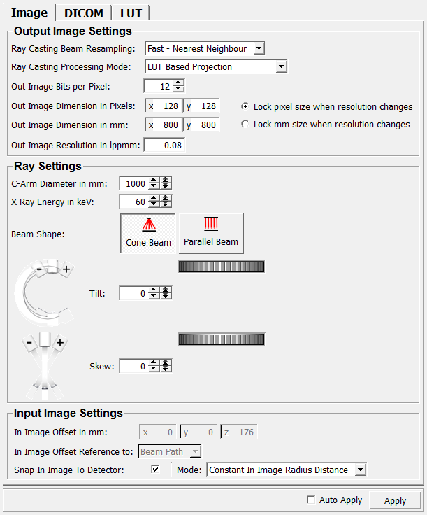
Parameter Fields
Field Index
Apply: Trigger |
In Image Offset Reference to: Enum |
Ray Casting Beam Resampling: Enum |
Auto Apply: Bool |
inImageValid: Bool |
Ray Casting Processing Mode: Enum |
Beam Shape: Integer |
Maximum X-Ray Energy In keV: Integer |
Resolution Lock Mode: Enum |
C-Arm Diameter in mm: Integer |
Minimum X-Ray Energy In keV: Integer |
Skew: Integer |
dontAutoCalcImageSize: Bool |
Mode: Enum |
Snap In Image To Detector: Bool |
Drop Window Center: Integer |
Out Image Bits per Pixel: Integer |
Tilt: Integer |
Drop Window Maximum Height: Double |
Out Image Dimension in mm: Vector2 |
X-Ray Energy in keV: Integer |
Image Laterality: String |
Out Image Dimension in Pixels: Vector2 |
|
In Image Offset in mm: Vector3 |
Out Image Resolution in lppmm: Float |
Visible Fields
Ray Casting Beam Resampling
-
name:beamResamplingMode, type:Enum, default:Fast - Nearest Neighbour¶ Defines how the input image voxels are collected that are part of a single beam.
Values:
| Title | Name |
|---|---|
| Fast - Nearest Neighbour | Fast - Nearest Neighbour |
| Exact - Siddon | Exact - Siddon |
Ray Casting Processing Mode
-
name:processingMode, type:Enum, default:LUT Based Projection¶ Defines how each passed voxel has an effect on the resulting projected value.
Values:
| Title | Name |
|---|---|
| Mean Extinction Projection | Mean Extinction Projection |
| Maximum Extinction Projection | Maximum Extinction Projection |
| LUT Based Projection | LUT Based Projection |
Out Image Bits per Pixel
-
name:outImageBitsPerPixel, type:Integer, default:12, minimum:1, maximum:16¶ Sets the gray value depth in bits per pixel.
Resolution Lock Mode
-
name:resolutionLockMode, type:Enum, default:Lock pixel size when resolution changes¶ Defines which unit shall be left unchanged if the resolution changes.
Values:
| Title | Name |
|---|---|
| pixel size when resolution changes | Lock pixel size when resolution changes |
| mm size when resolution changes | Lock mm size when resolution changes |
C-Arm Diameter in mm
-
name:cArmDiameter_in_mm, type:Integer, default:1000¶ Sets the distance between the beam source and the beam detector in mm.
Tilt
-
name:tilt, type:Integer, default:0, minimum:-180, maximum:180¶ Sets the rotation of the beam around the z-axis of the 3D input image in degree (+/- 180° rotation).
A positive angle indicates a counter-clockwise rotation and a positive angle indicates a clockwise rotation.
Skew
-
name:skew, type:Integer, default:0, minimum:-45, maximum:45¶ Sets the rotation of the beam path around the x-axis of the 3D input image in degree.
This parameter is limited to +/- 45°.
Currently disabled.
In Image Offset in mm
-
name:inImageOffsetIn_mm, type:Vector3, default:0 0 176¶ Sets the dislocation in mm of the rotation center which is in the input image’s center by default.
Affects
In Image Offset Reference to.
In Image Offset Reference to
-
name:inImageOffsetMode, type:Enum, default:Beam Path¶ Defines how the
In Image Offset in mmis interpreted.
Values:
| Title | Name | Description |
|---|---|---|
| World | World | The offset takes effect in direction of the input image’s main axes. 
|
| Beam Path | Beam Path | The offset takes effect relative to the beam path. 
Hint: this option dislocates the output image independetly from the beam path settings. A 100 mm offset in x-direction in this mode mode always pushes the output image 100mm to the right, regardless what beam path rotation is selected. A 100 mm offset in World mode causes different positions of the output image depending on the beam path, because the input image might move out of the beam path. |
Snap In Image To Detector
-
name:inImageSnapToDetector, type:Bool, default:TRUE¶ If checked, the
In Image Offset Reference tois set to Beam and values are being calculated automatically.The x and y offsets are set to zero (thus adjusting them in image centered to the beam path) and the z offset is calculated with a result that moves the input image as close as possible to the detector without subtending it.
Checking this option makes the
Modeavailable.
Mode
-
name:inImageSnapToDetectorMode, type:Enum, default:Constant In Image Radius Distance¶ Defines the mode for automatic parameter calculation.
Values:
| Title | Name | Description |
|---|---|---|
| Constant In Image Radius Distance | Constant In Image Radius Distance | The distance to the detector is calculated based on the radius (= the maximum distance from the center to the edge) of the input image. This results in a constant distance of the in image center to the detector, regardless of the projection angle. This mode is ideal to get a series comparable images, because there is no angle related perspective distortion. 
|
| Minimum Distance | Minimum Distance | The distance from the input image to the detector plane is calculated to the smallest possible value. It depends on the angle of the projection. 
|
Auto Apply
-
name:autoApply, type:Bool, default:FALSE¶ If checked, all changes to any field computes the output image anew.
Image Laterality
-
name:imageLaterality, type:String, default:U¶ Sets the laterality of the image with a DICOM tag.
Minimum X-Ray Energy In keV
-
name:minimumXRayEnergy, type:Integer, default:60¶ Sets the minimum X-ray energy for calculating the drop window.
Maximum X-Ray Energy In keV
-
name:maximumXRayEnergy, type:Integer, default:160¶ Sets the maximum X-ray energy for calculating the drop window.
X-Ray Energy in keV
-
name:XRayEnergy, type:Integer, default:60, minimum::field:`minimumXRayEnergy`, maximum::field:`maximumXRayEnergy`¶ Sets the simulated X-ray energy in keV.
The closer the X-ray energy in keV value is to the
Minimum X-Ray Energy In keV, the steeper the descent of the drop will be. The closer it is to theMaximum X-Ray Energy In keV, the more gently the descent will be (until it disappears completely when energy = max energy):
Graph color Energy Yellow 60 keV Red 90 keV Blue 160 keV (Min energy = 60 keV, max energy = 160 keV, drop window center = 1300, drop window max height = 0.2)
Drop Window Center
-
name:dropWindowCenter, type:Integer, default:1300¶ Sets the center in x-direction of the drop window.
The value should be near to the first voxel values for bone tissue. It is scaled automatically when the
Out Image Bits per Pixelparameter is changed.
Drop Window Maximum Height
-
name:dropWindowMaxHeight, type:Double, default:0.2, minimum:0, maximum:1¶ Sets the limit of the drop window’s height to a maximum value.
The actual drop window height is calculated based on the energy settings (
Minimum X-Ray Energy In keVandMaximum X-Ray Energy In keV).
Beam Shape
-
name:beamShape, type:Integer, default:0¶ Defines the shape of the beam. Can be parallel or cone shaped.
Out Image Dimension in Pixels
-
name:outImageDimension_inPixels, type:Vector2, default:128 128¶ Sets the output image’s extent in pixel.