| 4.2. Implementing the Contour Filter | ||
|---|---|---|
 | Chapter 4. Implementing a Contour Filter |  |
| 4.2. Implementing the Contour Filter | ||
|---|---|---|
| | Chapter 4. Implementing a Contour Filter | |
We want to implement a contour filter that is composed of the following image processing pipeline:
Take an input image a.
Smooth the input image with an average kernel:
Average[image a] -> image b.
Dilate the smoothed image by means of a morphological kernel
operation: Dilate[image b] -> image c.
Subtract the smoothed image from the dilated and smoothed image:
Subtract[image c,image b] -> image d.
Show the filter output image d.
For this processing pipeline we need the following basic image operators:
Average operator: a search yields the module Convolution. From the description:
“Simple constant convolution filters like Average, Gauss, Sobel,
Laplace.”
Dilation operator: a search yields the module Morphology. From the description:
“Implements dilation and erosion filters that separately act on
single bits.”
Subtraction operator: a search yields various arithmetic
modules. How to decide which module is the correct one? When you add
the modules and have a look at the modules' help, you will find that
Arithmetic0 is for arithmetic
operations on scalars or 3D vectors, Arithmetic1 is for arithmetic operations on a
single image, and Arithmetic2 is for
arithmetic operations on two images. As we want to subtract two
images, Arithmetic2 is the correct
module.
Proceed as follows:
Add the modules Convolution,
Morphology, and Arithmetic2 to the network.
Alternatively you could find and add the modules to the network via the Modules menu:
via Modules → Filters → Kernel → Convolution,
via Modules → Filters → Morphology → Morphology and
via Modules → Analysis → Arithmetic → Binary → Arithmetic2.
The image we use as input has to be processed first via the Convolution module. After that, the resulting
convoluted image will be processed and also output directly to the
Arithmetic2 module where the two images
will be subtracted.
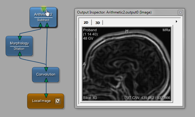
For the subtraction, the following information is offered in the
help of Arithmetic2: “The input
image 1 decreased by input image 2 is passed to the output.”
Therefore, it is important to connect the images in the correct order, otherwise the result will look rather strange.
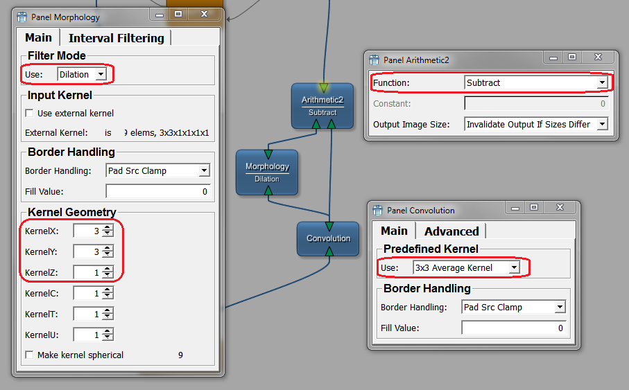
Open the panels of Convolution,
Morphology and Arithmetic2 by double-clicking the modules. Then
adjust/check the default values of the following parameters:
Module Convolution: Keep the
default kernel type "3x3 Average Kernel" for predefKernel.
Module Morphology:
In the
field Filter Mode, keep the default
value "Dilation".
For the Kernel Geometry, use a kernel of the size 3x3x1.
Module Arithmetic2: In the
field Function, change the default
value "Add" to the value "Subtract".
![[Tip]](images/tip.png) | Tip |
|---|---|
You can view and edit module field values also in the Module Inspector View. On the Fields tab, all fields of the currently selected module are listed by names and values. |
![[Note]](images/note.png) | Note |
|---|---|
Field names (in the module) and field labels (in the interface of the module panel) do not have to be the same. To find the field name, right-click the field label on the panel; the field name is listed as first entry of the context menu. |
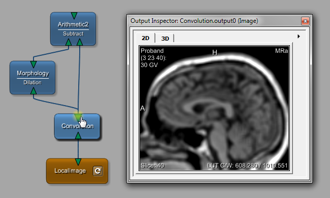
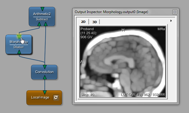
To view the results of every step in the processing pipeline, use the Output Inspector, which can be opened via the menu bar, View → Views. Click each connector to follow the image processing.
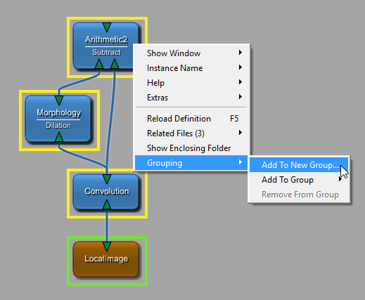
To distinguish the image processing pipeline, you can create a group for it. For that:
Select the three modules, for example by dragging a selection rectangle around them, or by single-selecting the modules while pressing SHIFT.
Right-click the selection to open the context menu and select Add to New Group.
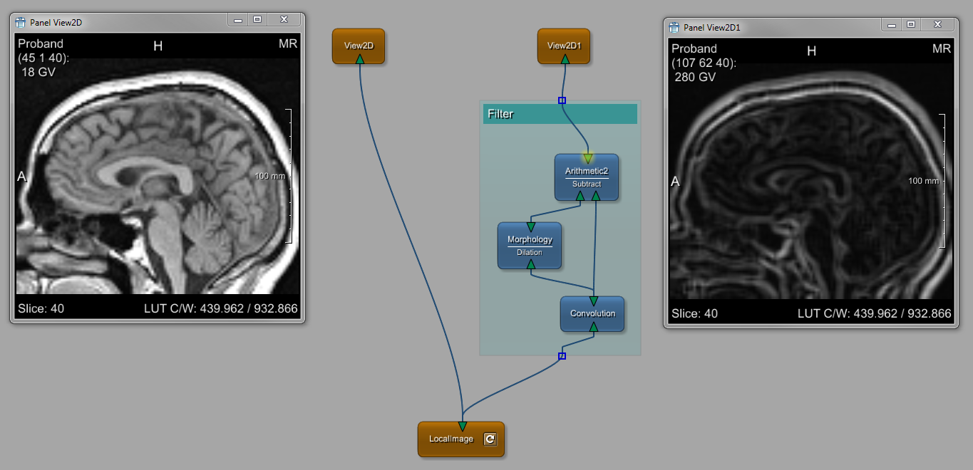
Enter a name for the new group, for example “Filter”.
The new group is created and displayed as a green rectangle. The group allows for quick interaction; for example, a double-click on its title bar zooms in and centers the group; a right-click on the title bar opens a menu for editing and deleting the group. You can also change the default color in the Preferences. For further information on groups, please refer to the MeVisLab Reference Manual, chapter “Using Groups”.
For the output, add another View2D module, either via the quick search or by
selecting the existing View2D module in
the network and duplicating it (via Edit → Duplicate or by pressing the keyboard shortcuts given there).
| Tip |
|---|---|
The filter can be tuned via some parameters given in the |
In a final step, we will synchronize the Viewers of the two View2D modules by establishing parameter
connections between them.
© 2025 MeVis Medical Solutions AG
| |  | |
| Chapter 4. Implementing a Contour Filter |  | 4.3. Parameter Connection for Synchronization |