TubularTracking
- MLModule
genre
author
package
dll
definition
keywords
Purpose
The TubularTracking module tracks the centerline and radius of a tubular structure, such as a vessel. The tubular structure must be bright on a darker background. Note that this module is work-in-progress and may be changed in the future.
Usage
The minimum input to the module is an input image and one start point (XMarker) for the tracking. Several start points can be provided as well as an initial direction for each point. XMarker points/vectors can be generated with the SoView2DMarkerEditor module. If no direction for an XMarker is supplied, a direction is found by analyzing the the local image orientation.
An optional binary input mask image can be supplied. This mask defines a valid region for the tracking. If no mask is supplied, the entire image volume is assumed valid.
There are a number of parameters controlling the tracking, see further below for more information. The Update button starts the tracking. Output is delivered in form of an XMarkerList with tracked positions and directions and an ML Graph structure which can be used for visualization with the SoVascularSystem module.
It is often beneficial to pre-process the input image, see Tips below for more information.
To export the tracking information, i.e., centerline points, radii and directions, the SaveBase module can be used to generate an XML-file from the vessel graph.
Details

The tracking employs a mathematical template model of a 2D or 3D tube, where the tube is bright on a homogeneous darker background (cf. illustration).
Details on the tracking algorithm can be found in the following paper:
O. Friman, M. Hindennach, H.-O. Peitgen Template-based Multiple Hypothesis Tracking of Small Vessels In: 5th International Symposium on Biomedical Imaging. 2008, pages 1047-1050
Tips
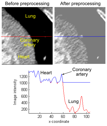
In some cases, the assumption of a homogeneous background is violated, as in the example illustrated here, where a coronary artery is running along the border between the heart tissue and lung tissue in a CT angiography image.
The background varies strongly, and the tubular template model will not fit well although the vessel is well contrasted. A simple trick here is to preprocess the input image to make the background more homogeneous. In the example to the right, the IntervalThresh module was used to segment and raise the intensity of the lung tissue to the intensity of the heart tissue, as shown by the intensity profiles before (red line) and after (blue line) preprocessing.
Windows
Default Panel
Input Fields
input0
- name: input0, type: Image
2D or 3D image data containing tubular structures
input1
- name: input1, type: Image
optional image mask of the same size as input0; zeros in the mask indicate forbidden areas for the tracking
inputInitPoints
- name: inputInitPoints, type: MLBase
list of start points (and optional directions) for tracking
Output Fields
outputGraph
- name: outputGraph, type: MLBase
graph structure as used in MeVisLab for representing vessel systems, e.g. used by the
SoVascularSystemmodule for visualization
outputTrackedPoints
- name: outputTrackedPoints, type: MLBase
list of XMarkers, where each XMarker contains a tracked centerline point and a direction vector of the local vessel orientation (The vessel radius is encoded as the length of the direction vector.)
Parameter Fields
Field Index
|
|
|
|
|
|
|
|
|
|
|
|
|
|
|
|
|
|
|
|
|
|
|
Visible Fields
Minimum Radius (mm)
- name: minRadius, type: Double, default: 1
minimum radius of the tubular structure (in millimeters)
Maximum Radius (mm)
- name: maxRadius, type: Double, default: 3
maximum radius of the tubular structure (in millimeters)
Initial Radius (mm)
- name: initRadius, type: Double, default: 2
radius used for initializing the tubular structure model at the seed point
The initial radius is also used for estimating the orientation (i.e. scale of Hessian estimator) for markers without vector component. If
Use Init Radiusis FALSE, (Minimum Radius (mm)+Maximum Radius (mm))/2 is used as initial radius.
Use Init Radius
- name: useInitRadius, type: Bool, default: FALSE
flag whether to use
Initial Radius (mm)
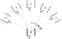
Number of Search Angles
- name: nbrOfSearchAngles, type: Integer, default: 3, minimum: 0, maximum: 20
The number of predictions to place between 0 degrees and
Max Step Angle. In the illustration, the number of search angles is 2 (giving a total number of angles equal to 2*2 +1 = 5). A reasonable spacing between search angles is 15-20 degrees, i.e., for a maximum search angle of 60 degrees, 3-4 search angles should be used.
Max Step Angle
- name: maxAngle, type: Double, default: 60, minimum: 0, maximum: 85
The maximum search angle indicates the maximum angle between 2 tracking steps (in degrees).
Pruning Threshold
- name: pruningThreshold, type: Double, default: 1
The pruning threshold is applied to the predictions to weed out the most unlikely ones. The goodness-of-fit is essentially a Student’s t-test, which can also be seen as a contrast-to-noise ratio. The threshold is applied to the predictions before they have been explicitly fitted to the image data using a Levenberg-Marquardt non-linear least squares fitting. Set this threshold low (e.g., -100) to investigate all predictions. A threshold of 0 to 3 can be used otherwise if the noise is spatially uncorrelated (e.g., white Gaussian noise). If the noise is correlated, which sometimes is the case in medical data due to smoothing, the threshold must be set higher.
Termination Threshold
- name: terminationThreshold, type: Double, default: 3
This threshold considers an entire sub-path (the length of the path is given by the Search depth parameter). The mean of the goodness of fit for the individual steps in the paths is calculated and compared with this threshold. As a rule of thumb, the termination threshold can be set twice as high as the pruning threshold. The idea is that whereas single steps can be allowed to have a low goodness of fit due to low image contrast, a path of several steps must exhibit a reasonable goodness of fit on average.
Max Number of Tracking Steps
- name: maxNbrSteps, type: Integer, default: 100
maximum number of steps to perform (cf.
Toggle Max Steps)
Max Length (mm)
- name: maxLength, type: Double, default: 100
maximum length in millimeters after which the tracking stops
Search Depth
- name: searchDepth, type: Integer, default: 3, minimum: 1, maximum: 10
Number of steps forward that will be searched for each hypothesized direction. A high value will give a more robust tracking, but the computational time increases quickly. Recommended values are between 3 and 5.
Step Length Factor
- name: stepLengthFactor, type: Double, default: 1, minimum: 0.01, maximum: 5
This factor determines the step length between the tracking points. The step length is calculated as the current radius times the step length factor. That is, the step length is not fixed, but varies with the radius so that longer steps are taken for larger structures.
Weight Window Factor
- name: windowSizeFactor, type: Double, default: 5, minimum: 3
This factor determines how large the Gaussian weight window is as a function of the radius: sigma = (weight window factor) * (radius). Generally, a larger window will give a more robust fit as more image data will be considered. However, a large weight window will also increase the computational time. In cases where there are interfering neighboring structures it may also be beneficial to keep the window size smaller. The default factor is 5.
Allow branching
- name: allowBranching, type: Bool, default: FALSE
When checked, the tracking algorithm will try to identify bifurcations.
Track bidirectional
- name: growBidirectional, type: Bool, default: FALSE
When this option is checked, the tracking will be started in two directions. (For XMarkers without direction vectors, tracking will always be carried out in two directions.)
Enable multiple hypothesis
- name: useMultipleHypotheses, type: Bool, default: FALSE
When this checkbox is unchecked, single hypothesis tracking will be performed, meaning that only one prediction of the next step is placed along the tangential line. This prediction is subsequently fitted to the image data.
When multiple hypothesis tracking is enabled, multiple predictions are placed as shown in the image below. Morover, hypothetical paths are recursively investigated (see search depth paramteter below). The multiple hypothesis approach requires more computational effort, but may improve results, especially in noisy and low contrast areas. Note, however, that the multiple hypothesis approach will not always give better performance as it also gives the algorithm more opportunities to find astray paths. If we have the prior knowledge that there is only one vessel with moderate curvature, no bifurcations and no other local disturbances, the single hypothesis tracking may give better results.
Toggle Max Steps
- name: toggleMaxSteps, type: Bool, default: FALSE
If this option is checked, the tracking will be terminated after
Max Number of Tracking Steps.
Toggle Max Length
- name: toggleMaxLength, type: Bool, default: FALSE
If this option is checked, the tracking will be terminated after
Max Length (mm).
Update
- name: update, type: Trigger
Starts the tracking. The input XMarkerList will be compared with the list of positions for which a tracking result already exists. Only for new points will a new tracking be carried out. This means that the tracking can be used in an interactive manner and the result is only updated with new start points instead of tracking everything new.
Clear
- name: clear, type: Trigger
Reset internal state completely